Download
1 / 33
1.17k likes | 2.69k Views
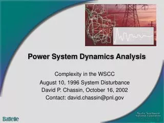
Introduction to Power System Analysis. ET2105 Electrical Power System Essentials. Prof. Lou van der Sluis. Test (1). The average power of the instantaneous power dissipated in an AC circuit is called Complex power S Apparent power |S| Active power P Reactive power Q. Test (2).

E N D
Introduction to Power System Analysis ET2105 Electrical Power System Essentials Prof. Lou van der Sluis Electrical Power System Essentials
Test (1) • The average power of the instantaneous power dissipated in an AC circuit is called • Complex power S • Apparent power |S| • Active power P • Reactive power Q Electrical Power System Essentials
Test (2) An inductive current leads lags the voltage A capacitive load supplies consumes reactive power Electrical Power System Essentials
Electrical Power System Essentials Outline • Introduction to Power System Analysis • The Generation of Electric Energy • The Transmission of Electric Energy • The Utilization of Electric Energy • Power System Control • Energy Management Systems • Electricity Markets • Future Power Systems Electrical Power System Essentials
The energy is stored in the Electromagnetic Field Electrical Power System Essentials
Why…? Why AC and not DC ? Why a sinusoidal alternating voltage ? Why 50 Hz (or 60 HZ) ? Why three-phase systems ? Electrical Power System Essentials
Why AC and not DC ? Break-even distance for HVDC Electrical Power System Essentials
Why a Sinusoidal Alternating Voltage ? Triangular, sinusoidal and block Electrical Power System Essentials
The choice of Frequency (1) 50 Hz and 60 Hz • Between 1885 and 1890 in the U.S.A.: • 140, 133⅓, 125, 83 ⅓, 66 ⅔, 50, 40, 33 ⅓, 30, 25 en 16⅔ Hz • Nowadays: • 60 Hz in North America, Brazil and Japan (has also 50 Hz!) • 50 Hz in most other countries • 25 Hz Railways (Amtrak) • 16⅔ Hz Railways • 400 Hz Oil rigs, ships and airplanes Electrical Power System Essentials
The choice of Frequency (2) 50 Hz and 60 Hz • A too low frequency, like 10 or 20 Hz causes flicker • A too high frequency • Increases the hysteresis losses: • Increases the eddy current losses: • Increases the cable and line impedance Electrical Power System Essentials
Three Phase Systems (1) Phase voltages in a balanced three-phase system (50 Hz) Electrical Power System Essentials
Three Phase Systems (2) The magnetic field generated by a three-phase system is a rotating field Electrical Power System Essentials
Some basics 3 phase systems Power Voltage levels Phasors Per unit calculation Power system structure Electrical Power System Essentials
Three Single Phase Systems One Three Phase System Electrical Power System Essentials
Balanced Three Phase System (1) Vc Ic Va Ib Ia Vb • Voltages in the 3 phases have the same amplitude, but differ 120 electrical degrees in phase • Equal impedances in the 3 phases Electrical Power System Essentials
Balanced Three Phase System (2) Vc Ic 0 Va Ic Ia Ib Ia Ib Vb Electrical Power System Essentials
Balanced system Single Phase calculation Vc Ic 120º Va Ib Ia 120º Vb Electrical Power System Essentials
Line-to-Line Voltage Electrical Power System Essentials
Three Phase Complex Power • 3 x 1-phase complex power Electrical Power System Essentials
Power (1) P: Active power (average value viR) Q: Reactive power (average value viX) Electrical Power System Essentials
Power (2) I* V I Negative How to calculate P and Q from the voltage and current phasor ? • Inductive load consumes reactive power (Q>0) • Current lags the supply voltage • Capacitive load generates reactive power (Q<0) • Current leads the supply voltage Positive Electrical Power System Essentials
Power (3) Electrical Power System Essentials
Series / Parallel Electrical Power System Essentials
Power Factor Power factor That part of the apparent power that is related to the mean energy flow Electrical Power System Essentials
System Voltage Levels Electrical Power System Essentials
Steady State Analysis: f = 50 Hz 6000 km L C/2 C/2 • f = 50Hz = v/f = 3e8/50 = 6000km • Modelling with R, G, L and C Electrical Power System Essentials
Steady State Analysis (1) 50 V 100 30° 86.6 Example: Electrical Power System Essentials
Steady State Analysis (2) Power System Electrical Power System Essentials
Phasor/Vector Calculus Real/imaginairy part: Addition/substraction Length/angle: Multiplication/division Electrical Power System Essentials
Network Elements Electrical Power System Essentials
Time Phasor Current in phase U = IR Current lagging U = jLI Current leading I = jCU Electrical Power System Essentials
Per-Unit Normalization • 156150 V 1.041 pu (150000 V = 1 pu) • Advantageous to calculating with percentages • 100% * 100% = 10000/100 = 100% • 1 pu * 1 pu = 1 pu • Define 2 base quantities Example: Electrical Power System Essentials
Power System Structure Electrical Power System Essentials