Download
1 / 34
370 likes | 709 Views
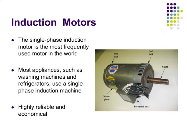
VisSim for Electric Motor Control Visual Solutions, Inc. 487 Groton Road, Westford MA 01886 USA (800) VISSIM-1 www.vissim.com. VisSim Supported Motors. AC Induction BLDC Brush PMSM Stepper Switched Reluctance. TI-Based Motor Control Blocks. Sensored AC Induction Control Blocks

E N D
VisSim for Electric Motor ControlVisual Solutions, Inc.487 Groton Road, Westford MA 01886 USA(800) VISSIM-1www.vissim.com
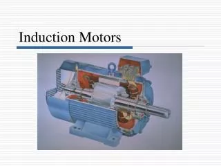
VisSim Supported Motors AC Induction BLDC Brush PMSM Stepper Switched Reluctance
TI-Based Motor Control Blocks Sensored AC Induction Control Blocks V/Hz Profile Generator Sensorless AC Induction Control Blocks AC Motor: Simulated ACI Motor ACI Speed Estimator: Speed estimation from phase currents ACI Flux Estimator Current Model PMSM Sensorless Control Blocks Phase Voltage Calc SMO Position Estimator
General Transforms • Clarke & Inverse Clarke Transform • For balanced three-phase circuits, the Clarke transform is the projection of three-phase AC signals (phase currents) to two stationary orthogonal signals • Park & Inverse Park Transform • For balanced three-phase circuits, the Park transform is the projection of stationary 3-phase AC signals two axes rotation with the same frequency as the original signal. This results in two DC quantities easier to use for control before performing the inverse transform back to AC values for the PWM. • PID Regulator • PWM Wave Form Generator • Space Vector Generator (Quadrature Control) • 2nd harmonic wave form generator w/D+ Q inputs • Space Vector Generator (Magnitude/Frequency) • 2nd harmonic wave form generator w/ Mag+Freq inputs • Space Vector PWM: Used for 2812 PWM modulation
Rotational Sensors • QEP Speed • Takes normalized unit sawtooth and produces fraction of max speed • To normalize, apply gain of 1/<max counts> to EQEP output • Resolver Decoder • Resolver is like rotating transformer. Base carrier frequency is picked up by sensing coils at 90 deg. Carrier freq is filtered out, and atan2 of 2 coil intensities gives rotor angle. • Speed Calculator • Takes event capture count as input, produces fraction of max count as result • Enter max count (interval between edge event) as block parameter
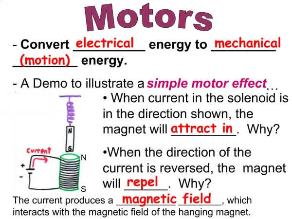
Stepper Motors Multiple "toothed" electromagnet statorsaround gear-shaped magnet or iron core rotor (switched reluctance) Each stator coil is slightly offset from the next By energizing each winding in turn, you move the rotor a bit Order of energizing gives rotational direction Used with open-loop positioning since it can be assumed that the rotor turns a discrete amount with each pole activation A unipolar stepper motor has two windings per phase, one pole per winding Bipolar motors have single winding per phase, 2 poles per winding. Must use H-bridge to reverse polarity
Stepper motor wave forms To output waveform from DSP, write sequence of bit patterns to GPIO port. Wave Drive – one coil energized at a time Full Step – two coils Less smooth, more power, more torque Half Step – alternates one and two coils Hybrid, 2x steps
VisSim for Stepper Motor Control Use case block to select hex constant for GPIO pattern sequence Use counter to drive case block Output of case connects to GPIO write
Stepper Control Issues Rate of pole switching controls rotational speed Rate is limited by rated torque and load – If you switch too fast, you will not rotate maximum start frequency rating at no load maximum start-stop torque is the pull-in torque pull-out torque is max torque without losing steps step rate is ramped up during start Use variable frequency ramp block for stepper speed control
VisSim/Motion Extensive block set for simulation of electric motor systems Supports AC induction, brush and brushless DC motors Stepper motors Low level PWM switching simulation level Selection of Sensors, Loads, Controllers, Transforms
Brush DC Motors Commutation done mechanically Simple to control, but brushes wear over time Low cost Rotor has multiple coils, stator can be permanent magnet or coils. Magnets lose strength over time
BDC motor types Shunt-Wound – stator coils in parallel to rotor coils Current in stator and rotor are independent. Good for speed control Series-Wound – stator coils in series with rotor coils Good for high torque since current in stator and rotor increases at same rate Wound stators does not suffer torque degradation like permanent magnet stator
BDC directional control Requires H-bridge to reverse polarity of supply Ifwd = forward motion, Irvs = reverse, Ibrk = braking Need grounding R’s to avoid shorts on startup
BDC Speed Control BDC motor speed is proportional to voltage Motor coils act as low-pass filter for PWM so voltage is proportional to PWM duty cycle Frequency of PWM an issue Too low a frequency results in audible noise at low speed and sluggish response Too high a frequency loses efficiency due to switching losses 4 to 20 kHz is typically used
Feedback control For speed control, use speed sensor with PID feedback control QEP speed block needs “normalized” QEP input. (QEP / encoder tick count) for fraction of complete revolution Use enabled blocks for forward and reverse PWM configuration
Motion Trajectory Trapezoidal - spec max vel, max accel Diagrams>Examples>Applications>Motion>TrapezoidalProfile.vsm Linear acceleration from stop to max vel, hold max vel to stop zone, constant deceleration to stop S-Curve - spec max vel, max accel, max jerk Diagrams>Examples>Applications>Motion>S-curveProfile.vsm Linearly increase acceleration from stop to max accel, hold max accel, then decel to max vel, hold max vel to stop zone, linearly increase deceleration to max decel hold max decel, then decrease decel to stop Smoother, more computation
PID Tuning • ParameterUnknown blocks for PID terms • Use overshoot penalty to find stable solution • Use sliders with simple plant in auto-restart mode to examine the PID response space • Good paper “PID Control System Analysis & Design” Feb 2006, IEEE Control Systems Magazine Effects of independent P, I, and D tuning on closed-loop response. • derivative term can degrade stability if plant has transport delay • 80% of PID controllers in use have the derivative part switched off
PID structures Simple 3 term: y = e(x)(Kp + Ki/s + Kds) Implement s (d/dx) via zero/pole, zero gives derivative, pole is tuned for low pass filter. If Ti ≥ 4TD can do series PD-PI: y =e(x)(α + TDs) KP(1 +1/αTis) Where α =(1 ± √(1 − 4TD/ Ti ) )/2 > 0 Examine response w/autorestart, sample plant, and sliders for gains. Can be helpful to fix d/dt coef by hand and opt P and I
State Transition Block Allows creation of any number of states Each state has any number of transition conditions to change to another state Conditions are written in C code and may reference VisSim variables (must be syntactic C – no space or punctuation in name) Block output is current state, and rule that last fired to enter this state VisSim lets you use state names anywhere you can use expressions, like const and expression blocks
Scaled Fixed-Point Operations Arithmetics (add,mul,div,gain etc) Limit, unit delay, merge, map, PI regulator Hands-on Make sample diagram of sin->FixPt gain->plot run - observe high/low values in block. Change scaling to 13.16. Run. Observe plot Change sin amplitude to 4, scaling to 1.16 Run. Enable Tools/FixedPoint Configure… Autoscale. Rerun.
VisSim/Embedded Controls Developer Bundle of VisSim, C-Code, C2000 target, TI DMC block-set , fixed-point block set, TI Code Composer Studio plug-in Supports F280x, F28 MSP430, F2812 on-chip peripherals: Analog in, PWM, CAN, encoder, event capture, serial, SPI, I/O ports, watch dog
Debug, Test, and Validate • Minimize time spent in debug and test • Use high-level, pre-debugged blocks • Support simulation of controller at block level on PC • Allow mouse probe of every input and output to display values at any instant • Debug block-level simulation on PC
Debug and Validation • Pure simulation plus DSP-in-loop simulation and block level monitoring gives rapid feedback of controller response VisSim on PC C2000TM DSP (I/O Only) Peripheral Input Blocks Peripheral Output Blocks External Hardware VisSim block diagram DMCBlocks Fixed-PointBlocks UserBlocks Standard Blocks • Test DSP based controller against virtual plant on PC using JTAG HotLink • Inject plant failure modes to test controller response • High/Low watermark on fixed-point blocks gives numerical “headroom” safety factor • Interactive DSP utilization gives continuous CPU load factor • Interactively Change DSP controller gains from VisSim and plot DSP response.
Debug and Validate • Rapid diagram edit-compile-download-debug cycle (under 10 secs) *Code automatically generated, compiled, linked, and downloaded VisSim on PC VisSim Interface block downloads and monitors code running on DSP Control Application Code* JTAG Plant Under Control C2000Peripherals • VisSim blocks for: • Virtual plant • Interactive gains • Plots of DSP response C2000 DSP • DSP-in-loop simulation of controller at code level on DSP through automatic code generation, compile, link, and download, and using JTAG in Real-Time Monitor mode • Test, debug, and validate the complete control system executing on DSP using an interface block • Provide test input vectors and observe DSP results in VisSim on PC
Build AC - induction DSP in loop Open AC induction motor speed control system C:\visSim50\Embed_Controls_Developer\c2407(2812)eZdsp\QuickStart\acim_spd_control_qs.vsm Run and observe pure simulation results Select controller, click Tools/Codgen…, click “Include VisSim Comm Interface” Push “Codegen” button 7
Insert DSP component Delete simulated controller Insert VisSim/DSP|C2407(F28xx)|DSPinterface block Wire up in diagram same as simulated controller Save diagram as <filename>-d.vsm
Add blinking LED to controller Add blink logic to sim model Hint LED connected to C0 (2407) or F14 (F2812) Re-codegen Re-rerun DSP based version Compare F2812 waveforms to LF2407 Difference is due to increased JTAG delays in 2407 part
Burn FLASH Create FLASHable blink program and burn to flash.Note that 2812 must use Spectrum Digital FLASH utility.
Break 15 min
Basic pressure-flow system Pressure differential causes flow Integral of flow into a volume gives current mass occupying the volume Pvolume = nRT/V
Review of User Diagram Look at specific customer diagram
On-chip peripherals All on-board DSP peripherals supported including:analog inputs (outputs on EVM)digital inputs and outputssimple PWMs and full compare PWMsquadrature encoderevent capture, watch dog, interrupt, CAN busserial portSPII/O ports
TI Digital Motor Control (DMC) Library written by TI in C-callable assembler hand-written, tested and optimized by TI available in VisSim/ECD in easy-to-use block set supports simulation mode (pure PC based simulation with 16-bit truncation effects) supports code generation mode
Custom Block Creation VisSim DLL Wizard for MSVC Automatically creates project with code for creating block, naming block, pin count and pin names, data types, dialog for parameters VisSim exported function vissimRequest() allows query of VisSim properties: current time, time step, current block handle, block properties. DLL exported function: <my block>Event(eventCode, p1, p2) is called by VisSim on interesting events like sim start, end, step, code gen, mouse click