Download
1 / 55
560 likes | 694 Views
HCI 0283 Lecture 7 Connectivity. Data Visualisation. Connections. A class of phenomena exist whose underlying feature is that of connection

E N D
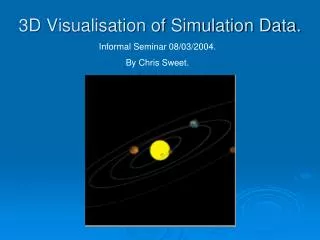
HCI 0283 Lecture 7 Connectivity Data Visualisation
Connections • A class of phenomena exist whose underlying feature is that of connection • The London Underground diagram focuses on connections as when travelling underground there is little point in considering geography – you can’t see it, so why include it in the diagram? • Earlier maps had shown the topology, but had considered geography to be more important
Connections • Other, less obvious, data sets can also be described in terms of their connectivity • Descriptions of wars found in historical or archaeological texts are, in effect, describing connections between nations • These descriptions also include useful information such as who attacked who
Warfare in Anglo-Saxon England Picts Northumbria Mercia West Saxon South Saxon Isle of Wight Kent Britons 620 650 680 Years AD
Connections • In many cases the basic connectivity information is enhanced by parameterisation • SO-grams (‘significant other’ grams) are based on topology but become richer when the types of relationships are added as parameters
SO-Grams Mary Gonz Andrew Dad Mark Kayte Syed ME Aunty June Nikolai Kevin Fred Wenllyn Penny Martin Diane
Connections • Organisation charts show connectedness of a special kind - personnel exist at clearly-defined levels within a hierarchy • Function call graphs of software systems show how the software runs – these can be used to generate effective compilation strategies • Communication networks are a good example of huge connected systems
Graph Theory • Connectivity is often studies in terms of graph theory • It is represented using a graph composed of nodes and connecting links • In the second lecture we looked at the connectivity of a small phone network • This could be shown as a disjoint graph identifying an absence of conversations between groups of people
H A B F K E G I J C M L D
Graph Theory • This representation can easily be parameterised to show directedness to form a directed graph • Links in a telephone network might show capacity, current traffic density, ratio of incoming to outgoing calls • Nodes may also be parameterised, such as aggregated incoming and outgoing calls
Graph Theory • Graphs of communication networks tend to be very large and complex • A major visualisation problem with these is that the graph can rarely be presented in two dimensions without crossovers and occlusions • Connectedness is treated in two ways • General networks • Tree networks
General Networks • A general network is one in which any node may be connected to any other node • This means that loops may occur in the graph • If each node is connected to every other node then the result is a fully-connected network
US Telephone Network • An example of this is the AT&T Long Distance telephone network • Over 110 nodes (switches) • Nearly fully-connected with over 12,000 links • Data concerning the performance of the network is collected every 5 minutes • Node data – aggregated incoming & outgoing traffic • Link data – traffic flow, capacity & overload
US Telephone Network • The appropriate visualisation technique to be used depends on the information being sought from the data • We may have a wide range of questions based upon the same data • As an example we will look at data for the day of the San Francisco earthquake, October 17th1989 • Such questions would include • Where are the overloads? • Which links are carrying the most traffic? • Was there any network damage? • Is there any underutilised capacity? • Are calls into the affected area completing or are they being blocked elsewhere in the network? • Is the overload increasing or decreasing?
Overload into and out of the Oakland node during the 1989 earthquake (coded as segment thickness and color, using bisected segments to show the directions)
Electronic Mail • Electronic mail networks are similar in many ways to phone networks • Geographical location is, however, no longer important • Offices may move, San Francisco will not! • HierNet uses node placement algorithms to automatically produce an uncluttered and insightful display
HierNet of email within an organisation – node size represents the aggregated volume of traffic, link colour represents the volume of emails
NetMaps • Graphs can represent connections between people, things and services • If I decide to borrow money from the bank to buy a house, then there are connections between me, the bank, the house and the house owner • Graphs representing these connections can be used for many purposes, including the detection of fraud • NetMaps allow you to plot all of these relationships and look for unusual patterns • In the UK, the Serious Fraud Office spent 8 man-years trying to identify the person behind a complex fraud case • It took a single user four weeks to identify the same person from the same data using NetMap
NetMaps • The basic NetMap display is a ring divided into segments, each of which represents a different category of entities, e.g. buyers, lenders, houses and so on • Relationships between entities are plotted with lines in the central area • The investigator can set rules so that the only lines displayed are those for which an item is connected to at least three others • Patterns then begin to emerge…
NetMaps • NetMaps are now widely used in detecting fraud worldwide • NetMaps also allow nodes to be displayed according to the way in which they are connected – step-link graphs • It can also be extended using bar charts for each segment • Such tools are commonly used in data mining
World Wide Web • The WWW is too large to try to represent as a graph in its entirety • Two user groups are interested in the connectivity of the web • Users (where have I been and how did I get there?) • Administrators (how are people getting to my site and is it the way I imagined?) • Administrators have much in common with telecommunication network specialists • Users may have several reasons for moving from one web page to another • Building up a cognitive collage • Searching for a well- or poorly-designed target • The probability that the next page visited has already been seen is about 58%
World Wide Web Browsing to form a cognitive collage Searching for a target
World Wide Web • A display of the user’s past trajectory (a trace) would be very useful, particularly if a single direct interaction can return the user to a previously visited page • Such a trace can be represented graphically and enhanced by encoding with colour, position, size and arrow direction • This can be extended to examine how large numbers of people travel between web pages; this can be useful for site designers
World Wide Web • As well as Where am I? and Where have I been? users want to know Where can I go now? • A look-ahead feature would be useful both as context and as a clue to where to go next • The walk2web (www.walk2web) tool provides a way to do this for any website showing the possible exits from a website and previews of the sites to which these will take you • This allows you to discover links which you might otherwise miss or which might surprise you • E.g. in March 2010 there was a link from the www.ruv.is homepage to the www.shaunthesheep.com homepage…
World Wide Web • A further question is Where should I go now? • This is an extremely difficult question to answer • Some clue or scent can be used to show what is available on a particular page • This can be done through category codes or footprints, popular routes through web sites • Another approach is to map out the network of relevant websites relating to a topic • TouchGraph (www.touchgraph.com) allows you to input asearch term and will then display a network of sites which contain information on that topic • Selecting a node will display a link to the article on the site
Tree Structures • All of the previous approaches can be used with networks that contain loops • The other form of connected data is represented by tree structures • Examples of tree structures include • Organisational hierarchies • ‘Normal’ directory structures • Trees are drawn from the root node down to the target node, and often refer to parent, sibling and child nodes
Designated root node Parent of A Sibling of A A Leaf nodes Child of A Leaf nodes
Cone Trees • Tree graphs take up a lot of space • Imagine a flat tree • A two-dimensional view of the data arranged in a cone is easier to handle
Tree Maps • Tree maps allow the structure of a tree to be spread across the entire area of a page or screen • A large rectangle represents the root node • This is then divided into sections representing the second generation nodes • Each second generation node is divided into sections for the third generation nodes
Hyperbolic Browser • This techniques allows the entire tree to be kept within a circular area • The method is based on a hyperbolic geometric transformation • The root node is initially displayed at the centre • Selecting another node brings it to the centre and morphs the rest of the display • This provides both focus and context