Download
1 / 21
220 likes | 423 Views
Radiation-Hardened re-programmable Field-Programmable Gate Array (RHrFPGA). A.B. Sanders 1 , K.A. LaBel 1 , J.F. McCabe 1 , G.A. Gardner 2 , J. Lintz 2 , C. Ross 2 , K. Golke 2 , B. Burns 2 , M.A. Carts 3 , and H.S. Kim 4 NASA/GSFC, Code 561.4 Greenbelt, MD 20771

E N D
Radiation-Hardened re-programmable Field-Programmable Gate Array (RHrFPGA) A.B. Sanders1, K.A. LaBel1, J.F. McCabe1, G.A. Gardner2, J. Lintz2, C. Ross2, K. Golke2, B. Burns2, M.A. Carts3, and H.S. Kim4 • NASA/GSFC, Code 561.4 Greenbelt, MD 20771 • Honeywell, Defense and Space Electronics Systems, Clearwater, FL 33764-7290 • Raytheon/ITSS, Lanham, MD 20706 • Jackson and Tull, Chartered Engineers, Seabrook, MD 20706
OUTLINE • Introduction • Radiation Test Suite • Test Configuration • Program Test Methods • Test Procedure • Test Results • Summary • Acknowledgements
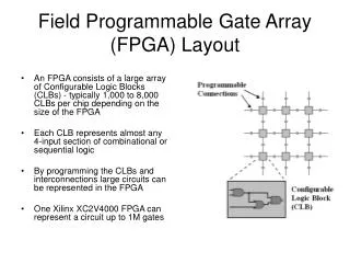
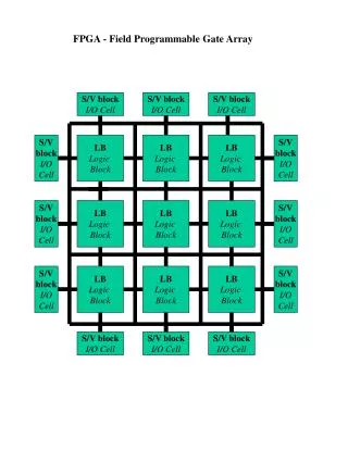
INTRODUCTION • Radiation-Hardened Re-programmable Field-Programmable Gate Array (RHrFPGA) by Honeywell • Configurable Logic Blocks provide functional elements for constructing user’s logic • I/O Cells provide the interface between the package pins and internal signal lines • Programmable Interconnect; Resources provide routing paths to connect the inputs and outputs onto the appropriate networks • Customized configuration is established by programming internal static memory cells that determine the logic functions and internal connections implemented in the FPGA INTERNAL FPGA
DEVICE CHARACTERISTICS • Characteristics: • Silicon Epi thickness is 0.2 m • Gate length is 0.35 m • Material thickness over the Silicon Epi equivalent to 8.3 m(Si) • Physical cross-sections of the memory and flip-flop cells are 0.45 m2 and 2.1 m2, respectively • SOI technologies offer greater speed and power reduction compared to conventional bulk CMOS • Motivation: Why Develop the RHrFPGA? • Reconfigurable FPGAs offer a significant advantage over one-time programmable Antifuse FPGAs • Cache Logic design allows part of the FPGA to be reprogrammed without loss of register data, while the remainder continues to operate without disruption • Rad hard need for space and military applications without complex external mitigation circuits (single chip solution)
BACKGROUND • BACKGROUND: Development of the RHrFPGA • In July 1998, Honeywell and Atmel announced the signing of a license for Honeywell to develop a radiation hardened version of Atmel’s 30,000 gate, 6400 register Field Programmable Gate Array (FPGA), the AT6010 • Honeywell developed a CMOS Silicon-On-Insulator (SOI) version of the AT6010 to meet the radiation hardness levels required for commercial and military space and missile systems • The radiation hardened FPGA development was funded and managed by NASA Goddard Space Flight Center
RADIATION TEST SUITE InterfaceCable • ‘Suite’ includes: PC, Cables, Custom Remote Terminal Unit (RTU) Interface Dongle (in Cable), and RTU Test Board (Sockets for RHrFPGA DUT, foreground) PC RTU Test Board
RTU Test Board Layout RHrFPGA ‘Device Under Test’ Socket (under Beam) Clock Input ‘Control’ RHrFPGA Socket (exercises DUT) Program & Command Input Error Output Power Input Parallel & Serial EEPROM Sockets for (opt.) On-card Config. Configuration Select Switches
ION BEAM CHARACTERISTICS RHrFPGA Heavy Ion Testing at Room Temperature at TAMU • Orientation: Test fixture was oriented so angular rotation was parallel to the gate width of the test devices’ transistors • Angular rotation was limited to 60 degrees due to fixture shadowing of the die at higher angles of incidence
RHrFPGA TEST PROGRAMS (Vectors) RHrFPGA Heavy Ion SEU Test Programs at TAMU
TEST PROCEDURE • Establish the correct test conditions • Load the RHrFPGA controller and test device with the proper configurations and verify test set functionality • Irradiate the test device to the desired effective fluence while monitoring the device for SEU and monitoring for proper health • Read the controller status registers to determine the number of upsets or test anomalies • Read the test device configuration to check for configuration SRAM upsets • Record all relevant test data from exposure run
HEAVY ION TESTING RESULTS • The test evaluated the RHrFPGA using eight different test programs and configurations • Seven were optimized for SEU testing to evaluate specific internal memory elements within the device and one test program represented a current RHrFPGA application • Nominal supply voltage is 3.3V and the devices were tested at the worst case voltage of 3V • Tests well below nominal (1.8V and 2.1V) were utilized to validate error detection • The RHrFPGA test devices did not experience SEU or other SEE to the maximum available test LET of 174 MeV·cm2/mg • Performed at minimum rated supply voltage of 3.0V • Applied all eight tests for fluences of 1.0x10⁷ ions/cm2 per test
PROTON TEST MOTIVATION AT IUCF • Memory Elements: The RHrFPGA memory elements use SEU hardening techniques similar, but harder than those of Honeywell’s HX6408 SRAM • The HX6408 SRAM proton sensitivity was shown to be dependent on the proton angle of incidence on the die • Sensitivity attributed a single secondary heavy ion hitting two transistors within a memory cell • The SEU cross-section is highest for a proton angle of incidence parallel to the path between the two sensitive transistors in a cell • A grazing parallel proton beam oriented normal to this path is thus expected to produce an SEU cross-section similar to a normal incidence beam. • The test irradiated the RHrFPGA with proton beam nearly parallel to the die surface • The die was oriented so that the beam was parallel to the sensitive path directions
POSITIONING ASSEMBLY AT IUCF • The rotation angle was limited to 70 degrees due to alignment constraints and concerns of irradiating the control device • All exposures were performed at a 70 degree angle of incidence • Different axes of rotation for the two cell types were used becausethe configuration RAM and application flip-flops are orthogonal to each other Positioning Assembly at IUCF
RAM CELL TEST Test Board in horizontal position with rotation about the vertical axis
FLIP-FLOP TEST Test Board in vertical position with rotation about the vertical axis
RHrFPGA TEST PROGRAMS (Vectors) RHrFPGA Proton SEU Test Programs at IUCF
PROTON TESTING RESULTS • The test evaluated the RHrFPGA using six different test programs and configurations • The test was optimized to evaluate the RHrFPGA’s two unique types of memory elements. • The RHrFPGA test devices were irradiated to a proton fluence of 3.4x10¹³ p/cm2 with 203 MeV protons • Test parts did not exhibit SEU or any other SEE, demonstrating that the RHrFPGA is essentially immune to proton-induced SEU
SUMMARY • Heavy Ion Testing • Two RHrFPGA devices did not upset to the maximum available test LET of 174 MeV·cm2/mg and an ion fluence of 1.0x10⁷ ions/cm2 • The test consisted of seventeen exposure runs at the minimum specified operating voltage of 3.0V • The test results were consistent with analytical predictions indicating a much higher minimum SEU LET threshold than could be obtained from a heavy ion SEU test • Proton Testing • Three RHrFPGA devices did not experience SEU or other SEE to a proton fluence of 3.4x10¹³ p/cm2 per test device • Test results were also consistent with analytical predictions indicating that the device is not sensitive to proton induced SEE
ACKNOWLEDGEMENTS The Authors would like to acknowledge the sponsors of this effort: NASA Electronic Parts and Packaging Program (NEPP), NASA Flight Projects, and the Solar Dynamic Observatory (Project). The Authors wish to acknowledge the following individuals for their contribution to this publication: Kenneth A. LaBel, Martha V. O’Bryan, Gary Gardner, and John Lintz.