Download
1 / 12
190 likes | 1.03k Views
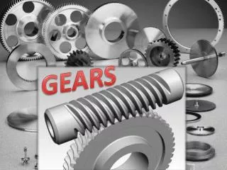
Gears. Transmits Rotary motion Torques. Why use teeth? Why not friction rollers? Teeth need to be specially shaped to allow smooth engagement. Involute curves are ideal. Spur Gear. Rack and Pinion Gear. Internal Gear. Helical Gear. Bevel Gear. Herringbone Gear. Worm Gear. Miter Gear.

E N D
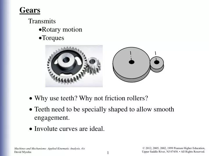
Gears • Transmits • Rotary motion • Torques • Why use teeth? Why not friction rollers? • Teeth need to be specially shaped to allow smooth engagement. • Involute curves are ideal.
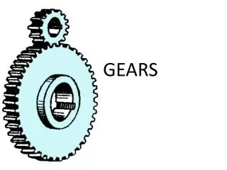
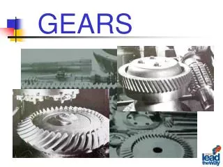
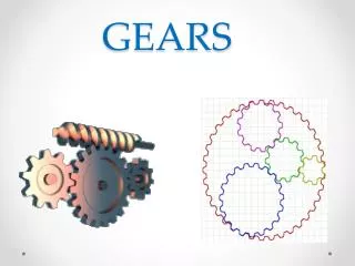
Spur Gear Rack and Pinion Gear Internal Gear Helical Gear Bevel Gear Herringbone Gear Worm Gear Miter Gear Types of Gears:
Involute tooth profile Base Circle Pitch circle Line of Centers Pitch circle Spur Gear Geometry: • Involute tooth • Unwind a string from a base circle • Track the path of the string end • Pitch Diameter (d) • Size of equivalent friction rollers
Number of Teeth (N) • Must be an integer value • Diametral Pitch (Pd) • size of a the gear tooth
Base Circle Pressure Line Pitch Circle Pressure Angle, f Pitch Line Pitch Circle Base Circle Line of Centers • Pressure Angle(f) Standard values: f = 14½0, 200, 250
Mating gears must have same pressure angle and diamtral pitch.
Tooth Thickness Pitch Diameter (d) Face Width (F) Tip Radius Face Fillet Radius Addendum (a) Flank Addendum Circle Circular Pitch (p) Pitch Circle Dedendum (b) Dedendum Circle • Others Features • Circular Pitch p = pd/N • Base circle db=d cos f • These features are standardized for interchangeability: • Addendum a=1/Pd • Dedendum b=1.25/Pd • Face Width F=12/Pd
Driver Gear (pinion) Base Circle Line of Centers Pitch Circle Pressure Angle, f Addendum Circle Center Distance, c Pitch Line 2 3 Base Circle 1 Pitch Circle Contact Line Addendum Circle Driven Gear • Mating Spur Gears :
1 2 Gear Kinematics: • Velocity Ratio (VR) • Gear Ratio + same direction - opposite direction 3:1 or “three to one” means VR = 3 Commonly written:
Gear Trains: • Several gear pairs are placed in series. • Why? • Train Value (TV) • TV = (VR)1 (VR)2 (VR)3 …
1 2 3 4 5 6 4 6 win 2 3 5 1 wout Example The gear train shown is used with an input speed of 1200 rpm, cw. Given the following properties: • N1=24, N2= 48 & Pd = 16 • N3=24, N4= 48 & Pd=12 • N5=15, N6= 35 & Pd = 10 Determine the output velocity and center distance of the gear train.
1 2 win 1 6 3 6 wout 3 5 2 4 5 4 Example The gear train shown is used with an input speed of 1200 rpm, cw. Given the following properties: N1=24 N2= 36 & Pd = 12 D3=2.0 in. & Pd=10 N4= 40 N5=16 & Pd=8 D6= 6.0 in Determine the output velocity and center distance of the gear train.