Download
1 / 37
500 likes | 1.16k Views
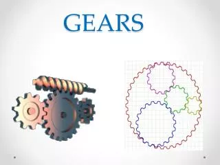
GEARS. The Unit Organizer. The Big Picture. Various Devices are used to Transmit Power and Motion. LAST UNIT/ Experience GDT. CURRENT UNIT Create Gear & Cam Mechanism Drawings. NEXT UNIT/ Experience Solid Modeling. UNIT SCHEDULE. Is about…. Gear & Cam Mechanisms.

E N D
The Unit Organizer The Big Picture Various Devices are used to Transmit Power and Motion LAST UNIT/ Experience GDT CURRENT UNIT Create Gear & Cam Mechanism Drawings NEXT UNIT/ Experience Solid Modeling UNIT SCHEDULE Is about… Gear & Cam Mechanisms We must be able to identify Requires that we understand… Cam Terms Types of Gears Requires that we understand… Gear Terms • Spur gear • Worm gear • Bevel gear • Rack gear • Root dia. • Pitch dia. • Outside dia. • Base circle • Pressure angle • Number of teeth • Involute profile • Addendum • Dedendum • Gear ratio • What purposes do gears serve and where are they used? • What are the features of a typical gear drawing? • What purpose do cams serve and where are they used? • What is the relationship between a cam profile and a displacement diagram? UNIT SELF-TEST QUESTIONS UNIT RELATIONSHIPS
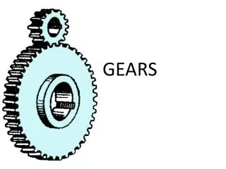
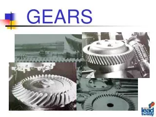
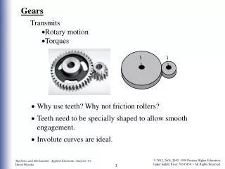
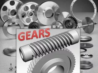
GEARS ARE USED TO TRANSMIT POWER AND ROTATING MOTION FROM ONE MACHINE PART TO ANOTHER. GEARS SPUR WORM BEVEL RACK
Spur Gear Spur gears operate on axes which are parallel. Click on the link below and view the gear in action. http://www.ericalbrecht.com/technic/fundamentals.html
Gear Ratio In the simplest case, a set of gears results in the same rotation speed on both the input and the output axle. This happens if both gears have the same number of teeth. However, in most cases gears are used to change the speed and mechanical advantage between axles. For simple gears calculating this gear ratio is simply a matter of counting the number of teeth on each gear and comparing by dividing the number of output teeth by the number of input teeth.
Gear Ratio For example, if the input gear has 12 teeth and the output gear has 24 teeth, then the gear ratio is 24/12 = 2. The standard nomenclature for this is to use a colon and relate the gear ratio to one, for example 2:1. INPUT GEAR OUTPUT GEAR
Worm Gear Click on the link below and view the gear in action. http://www.ericalbrecht.com/technic/fundamentals.html
Bevel Gear Click on the link below and view the gear in action http://www.ericalbrecht.com/technic/fundamentals.html
Rack Click on the link below and view the gear in action http://www.ericalbrecht.com/technic/fundamentals.html
Gear Applications Subaru Transmission LEGO Transmission
The Unit Organizer The Big Picture Various Devices are used to Transmit Power and Motion LAST UNIT/ Experience GDT CURRENT UNIT Create Gear & Cam Mechanism Drawings NEXT UNIT/ Experience Solid Modeling UNIT SCHEDULE Is about… Gear & Cam Mechanisms We must be able to identify Requires that we understand… Cam Terms Types of Gears Requires that we understand… Gear Terms • Cam • Follower • Displacement diagram • Spur gear • Worm gear • Bevel gear • Rack gear • Root dia. • Pitch dia. • Outside dia. • Base circle • Pressure angle • Number of teeth • Involute profile • Addendum • Dedendum • Gear ratio • What purposes do gears serve and where are they used? • What are the features of a typical gear drawing? • What purpose do cams serve and where are they used? • What is the relationship between a cam profile and a displacement diagram? UNIT SELF-TEST QUESTIONS UNIT RELATIONSHIPS
HOW CAMS WORK A Cam is a rotating part that changes rotating motion into reciprocating motion. FOLLOWER ROLLER CAM CAM SHAFT
HOW CAMS WORK A Cam is a rotating part that changes rotating motion into reciprocating motion.
HOW CAMS WORK A Cam is a rotating part that changes rotating motion into reciprocating motion.
HOW CAMS WORK A Cam is a rotating part that changes rotating motion into reciprocating motion.
HOW CAMS WORK A Cam is a rotating part that changes rotating motion into reciprocating motion.
HOW CAMS WORK A Cam is a rotating part that changes rotating motion into reciprocating motion.
HOW CAMS WORK A Cam is a rotating part that changes rotating motion into reciprocating motion. Click on the camshaft below and view the cams in action.
CAM DESIGN PROBLEM Instructions: Scale the drawing shown for all necessary dimensions. Then, using AutoCAD, create a cam that will move the Lever Arm roller to the position shown and then back to its original position in one 360 degree revolution. Refer to Fig. 20-19 in ‘Technical Drawing’ textbook for sample. Advanced: Create a solid model assembly of this mechanism.