Download
1 / 21
220 likes | 526 Views
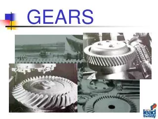
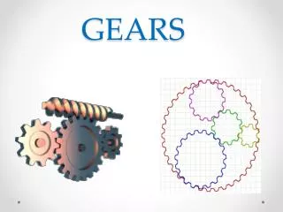
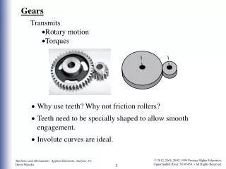
Gears. Different Gear Pairs. Spur Gears. Are used in transmitting torque between parallel shafts. Helical Gears. Are used in transmitting torques between parallel or non parallel shafts, they are not as noisy as spur gears. Bevel Gears.

E N D
Spur Gears Are used in transmitting torque between parallel shafts
Helical Gears Are used in transmitting torques between parallel or non parallel shafts, they are not as noisy as spur gears
Bevel Gears • Are used to transmit rotary motion between intersecting shafts Teeth are formed on conical surfaces, the teeth could be straight or spiral.
Worm Gears Are used for transmitting motion between non parallel and non transmitting shafts, Depending on the number of teeth engaged called single or double. Worm gear mostly used when speed ratio is quiet high, 3 or more
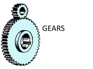
Nomenclature Smaller Gear is Pinion and Larger one is the gear In most application the pinion is the driver, This reduces speed but it increases torque.
pitch circle, theoretical circle upon which all calculation is based p, Circular pitch, p the distance from one teeth to the next, along the pitch circle. p=πd/N m, module=d/N pitch circle/number of teeth p= πm P, Diametral Pitch P=N/d pP= π
Angle Φ has the values of 20 or 25 degrees. Angle 14.5 have been also used. Gear profile is constructed from the base circle. Then additional clearance are given.
How Gear Profile is constructed A1B1=A1A0, A2B2=2 A1A0 , etc
REPRESENTATION OF GEARS As a fundamental principle, a gear is represented (except in axial section) as a solid part without teeth, but with the addition of the pitch surface in a thin long chain line. Teeth - Specify the teeth profile either by reference to a standard or by a drawing to a suitable scale. If it is essential to show one or two teeth on the drawing itself draw them as thick continuous lines
Bevel gear Root Spiral gear
- If mating gears are represented, the direction of the teeth should be shown on one gear only.
Assembly of gears External gears