Download
1 / 6
60 likes | 162 Views
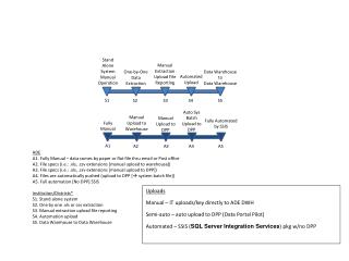
►INTSRUCTION 1. INSTRUCTION-----------------------------------------------------2 2. SAFETY PRECAUTION------------------------------------------2 3. SAFETY SYMBOL-------------------------------------------------2 ► PARTS AND FUNCTIONS

E N D
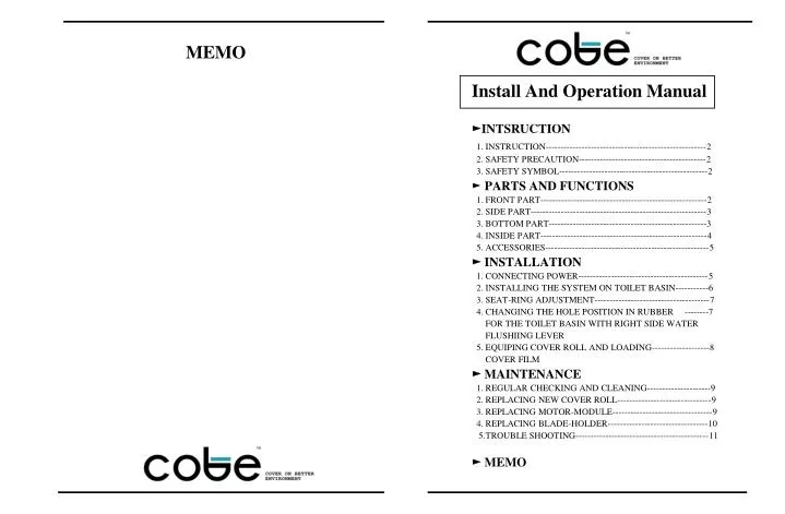
►INTSRUCTION 1. INSTRUCTION-----------------------------------------------------2 2. SAFETY PRECAUTION------------------------------------------2 3. SAFETY SYMBOL-------------------------------------------------2 ► PARTS AND FUNCTIONS 1. FRONT PART-------------------------------------------------------2 2. SIDE PART----------------------------------------------------------3 3. BOTTOM PART----------------------------------------------------3 4. INSIDE PART-------------------------------------------------------4 5. ACCESSORIES------------------------------------------------------5 ► INSTALLATION 1. CONNECTING POWER-------------------------------------------5 2. INSTALLING THE SYSTEM ON TOILET BASIN-----------6 3. SEAT-RING ADJUSTMENT--------------------------------------7 4. CHANGING THE HOLE POSITION IN RUBBER --------7 FOR THE TOILET BASIN WITH RIGHT SIDE WATER FLUSHIING LEVER 5. EQUIPING COVER ROLL AND LOADING-------------------8 COVER FILM ► MAINTENANCE 1. REGULAR CHECKING AND CLEANING---------------------9 2. REPLACING NEW COVER ROLL-------------------------------9 3. REPLACING MOTOR-MODULE---------------------------------9 4. REPLACING BLADE-HOLDER---------------------------------10 5.TROUBLE SHOOTING--------------------------------------------11 ► MEMO MEMO Install And Operation Manual
INSTRUCTION We highly appreciated in your choice of Cobe hygeine system..You are kindly requested to be familiar with these directions before install and use Clobe and always keep it together with the product. In case you are not clear about any directions or problems arising while using the product, please contact our service center. They will provide and support you with detailed instructions. 1. INSTRUCTION Cobe is the most updated model of the motorized hygienic toilet seats, eliminating common defects occurred in previous models. Cobe is developed for use in all public toilets where special sanitary conditions and low-maintenance are required: Airports, shopping malls, hotels, restaurants, sports-complexes, cultural and educational institutes, government buildings, office buildings, train and bus stations, etc. 2. SAFETY PRECAUTION Cobe Cover system is designed and made with consideration given to the safety of the users and subject and also to the safety of the unit. 1) This system must be installed only by, or under supervision of, a qualified person by Cobe . or his authorized dealers. 2) Do not modify the unit and system. If any modification is desired, ask Cobe. or its authorized dealer for service. 3) The unit has been factory-adjusted for optimum performance. Do not attempt to adjust any or switches except those specified in this manual for operation. 4) If you have experienced any trouble with the system, switch it off immediately, and contact Cobe. or its authorized dealer for assistance. 3. SAFETY SYMBOL This symbol identifies a safety note. Ensure you understand the safety notice and important notice before you install and use system unit. PARTS AND FUNCTIONS 1. FRONT PART 1) TOP COVER It protects and saves inside system units. 2) SENSOR AND SENSOR LENSE When a user approaches his or her palm over the sensor, film cover runs automatically for next use. . 3) 3 Digit FND It displays the balance uses of cover film. 4) SEAT-RING User can seat on this ring and the film cover is surrounded and rotated around this ring. ! ! 5. TROUBLE SHOOTING These instruction are intended to be performed by Cobe and it’s a authorized dealer’s service personnel. If any of these problems arise, please contact Cobe or their authorized dealers to resolve issue. . IMPORTANT NOTICE For EMERGENVY STOP of Cobe Cover, Press the SET BUTTON on the motor module 11 2
2.SIDE PART 6) SIDE-HOLDER It fixes top cover on system-body. 7) HARD WIRE It connects Battery-Pack with Adaptor for power supply in using hard wire connection mode. 3. BOTTOM PART 8) BLADE-HOLDER It cuts used cover film before rewinding on rewinding-reel. 9) MEDTAL BRACKET It fixes and connects the system unit on the toilet basin. 10) BOTTOM-LOCK (WRENCH BOLT) You can turn this bolt counterclockwise to open system body cover with key-unit 4. REPLACING BLADE-HOLDER When the blade has become dull or has gotten any troubles, change the blade-holder unit. 1) REMOVAL SCRAP BAR AND LOOSENING THE SEAT-RING FIXATIONS. Follow the same steps with above 3. SEAT-RING ADJUSTMENT in the PAGE 7 as below two steps and <FIGURE 6> in the PAGE7. First: Remove the scarp bar by loosening the screw, which fixed the scrap bar. Second: Loosen the two bolts, which fixed the seat-ring on the system-body. 2) PULLING THE SEAT-RING FORWARD Pull the seat-ring on forward and change the bottom parts from <FIGURE 13> to <FIGURE 14>. 3) CHANGE THE BLADE-HOLDER Then pull new blade holder from extra blade holder box in Figure 12 and remove the used blade holder by pulling-out and insert new blade-holder in the place . And assemble again reverse the order 2) SENSOR/LENSE 3) SENSOR HOLDER 4)FND DISPLAY 1) TOP COVER 5) SEAT-RING <FRONT VIEW> EMPTY REWINDING-REEL CUT-OFF SWITCH JACK ROLL-COUNTER MOTOR MODULE SUPPORTER <REPLACE MOTOR-MODULE / FIGURE 12> 1) TOP COVER 6) SIDE HOLDER NEW BLADE-HOLDER 7) HARD WIRE 9) METAL BRACKET USED BLADE-HOLDER <SIDE VIEW> <BOTTOM VIEW OF SEATRING /FIGURE 13> <BOTTOM VIEW OF SEATRING /FIGURE 14> 10 3
***IMPORTANT NOTICE: For EMERGENCY STOP of Cobe Cover, press the SET-BUTTON on the Motor Module. ► MAINTENANCE 1. REGULAR CHECKING AND CLEANING After buying and installation the system, regularly check the system status for maintenance and the balance cover roll uses for cover roll replacement. Regular cleaning the system will make optimal efficiency of the system and it’s long-term service life. 2. REPLACING OF NEW COVER ROLL When equipped cover roll is used up, remove the re-winded cover film roll reel from right chamber and move the finished cover roll reel (Empty Reel) from left chamber to right chamber. 4. REPLACING MOTOR-MODULE When the motor has gotten out of order or has had mechanical trouble, please immediately contact Cobe. or his authorized dealers for service. If Cobe or his authorized dealer has found any reason to change the motor-module, take next steps to replace. 1) Open the system body as <FIGUER 8> on the PAGE 8. 2) Separate the cover roll reel and the rewinding reel from the system. 3) Separate the cut-off switch jack from the motor-module. 4) Separate the roll-counter from the system. 5) Pull on the motor-module supporter forward and take out the motor-module from the system-body simultaneously. See below <FIGURE 12>. ! 4.INSIDE PART 11) MOTOR-MODULE It contains operating motor and battery or battery-pack.(4AAX2 alkaline battery) 12) MOTOR-MODULE SUPPORTER It fixes motor-module in system body. 13) ROLL AND ROLL-REEL It is new or balancing cover film roll wound on reel. 14) REWINDING-REEL It is for rewinding of used cover film. 15) CUT-OFF SWITCH JACK During a user sits on the system unit, it makes stop the sensor operating for rotating cover film. Therefore, during a user sits on, the system does not runs for changing cover film. 16) ROLL-COUNTER It counts the quantity of cover film consuming and balancing. 17) GUIDE-BAR It supports cutting of used cover film by under blade and sustains tightly rewinding of used cover film. 5) SEAT-RING 8) BLADE-HOLDER 10) BOTTOM LOCK (WRENCH BOLT) SENSOR LCD WINDOW SET RUN <BOTTOM VIEW> <RIGHT SIDE BOTTOM VIEW / FIGURE 10> <SET & RUN BUTTON ON THE MOTOR-MODULE / FIGURE 11> 11) MOTOR-MODUEL 13) ROLL & ROLL REEL 14) REWINDING-REEL 15) CUTT-OFF SWITCH JACK 17)GUIDE-BAR 15) ROLL-COUNTER 12) MOTOR-MODULE SUPPORTER <INSIDE VIEW> 4 9
5. ACCESSORIES 18) 2 ADJUSTERS They are for installation of the system unit on the toilet basin. They are assembled on the toilet basin by screwing bolts and nuts into the two holes of toilet basin. 19) 2 BOLTS & 2 NUTS They are for connecting 2 adjusters on toilet basin. 20) 2 WASHERS They are for connecting 2 adjusters on toilet basin, too. ***IMPORTANT NOTICE: TAKING INVENTORY Please check above accessories and parts with Assembled System unit are fully included in your packing! INSTALLATION 1.CONNECTING POWER ! ***IMPORTANT NOTICE: Power supply must be UL-CSA approved in USA territories; CE approved in EU territories and in each territory, necessary CERTIFICATE approved 6Volt DC, 2AMP-Type Adaptor. Wires must be encased in a conduit, raceway or equivalent system. Supply of local current is necessary. Minimum 18gauge wire possible to use. HARD WIRE CONNECTION For power supply by hard wire connected pack, take next steps First: Connect approved Adaptor (OUT-PUT: 6Volt, 2AMP Type) with hard wire. Second: Connect the Adaptor to electric-socket in toilet as like <FIGURE 01>(If there is no electric-socket, please contact to authorized electric engineer to install the socket near toilet basin) ! ! 2) EQUIPING COVER ROLL AND LOADING COVER SURROUNDING SEAT-RING To equip and load cover roll surrounding the seat-ring, take next steps. First: Insert cover roll between the roll-holding hole of motor-module and the metal roll-holder in left chamber as like <FIGURE 09>. Second: Pull the cover film out under roll-counter and upholster the seat-ring with the cover film. Third: Cover whole seat-ring till right edge of the seat-ring with the cover film. Fourth: Pull the cover film out through the blade-holder under right edge of the seat-ring as like <FIGURE 10>. Fifth: Pull the cover film out under the scrap bar and wind the cover film on the empty rewinding-reel from back of the reel to the direction of clockwise arrow in the <FIGURE 10>. Sixth: Press the RUN-button on the top of the motor-module and spin the roll-reel and the empty rewinding-reel for well winding of used cover film around the empty rewinding-reel and upholstering cover film surrounding the seat-ring. Last: By the SET-button, set equipped roll quantity. The digit is inputted and changed by the button in 200, 100, by turn. See <FIGURE 11>. 18) 2 ADJUSTERS BOTTOM LOCK (WRENCH BOLT) BLADER-HOLDER 19) 2 BOLTS & 2 NUTS 20) 2 WASHERS <BOTTOM VIEW OF THE SYSTEM / FIGURE 08> HARD WIRE < SYSTEM UNIT/ FIGURE 01 > EMPTY REWINDING-REEL CLOCKWISE ARROW COVER ROLL GUIDE BAR ROLL-COUNTER <EQUIP COVER ROLL / FIGURE 09> 8 5
2. INSTALLING THE SYSTEM ON TOILET BASIN 1) REMOVAL EXISTING TOILET SEAT & COVER Remove existing toilet seat and cover from toilet basin as like <FIGURE 02>. Then you can find two holes for connecting with the system unit. 2) JOIN 2 ADJUSTERS AND BOLTS TO THE METAL BRACKET Join 2 adjusters and bolts to metal bracket as like <FIGURE 03>. 3) PUT THE SYSTEM UNIT ON TOILET BASIN Put the system unit including connected metal bracket and bolts on the toilet basin as like <FIGURE 04>. Put the two bolts into the two holes of toilet basin. ARROW-WISE 4) CONNECT THE SYSTEM WITH TOILET BASIN. To connect and fix the system unit and toilet basin, screw bolts through the toilet basin hole with nuts as like <FIGURE 05>. 3. SEAT-RING ADJUSTMENT The system’s seat-ring has been factory- adjusted to fit on the normal size toilet basin. To fit the seat-ring to Elongated-Toilet Basin (Bowl), take next steps as <FIGURE 06>. First: Remove scrap bar by loosening the screw, which fixed the scrap bar. Second: Loosen the two bolts, which fixed the seat-ring on the system body. Last: Pull the seat-ring on forward for adjusting and assemble again reverse the order 4. CHANGING THE POSITION OF RUBBER HOLE IN SENSOR LENSE FOR THE TOILET BASIN WITH RIGHT SIDE WATER FLUSHIING LEVER To change the position of rubber hole in sensor lense, take next steps. First: Lift up the top cover as like <FIGURE 07>. Second: Hold the top cover by both hands and put it up to arrow-wise pulling the dark circle area to forward <FIGURE 07>. Third: See inside top cover and pull out the rubber from stainless plate and push it back changing the hole in the rubber from right to left 5. EQUIPING COVER ROLL AND LOADING COVER FILM 1) OPEN THE TOP COVER To open the system-body cover, unlock the bottom-lock (Wrench Bolt) in the bottom of the System-body. Just turn the bottom-lock to counterclockwise by the key unit as like <TOP VIEW OF TOILET BASIN / FIGURE 02> BOLT ADJUSTER TOILET BASIIN NUTS WASHER <CONNECTING DETAILS / FIGURE 05> METAL BRACKET <BOTTOM VIEW OF METAL BRACKET / FIGURE 03> GUIDE BAR BOLT ADJUSTER SEAT-RING ( PULL FORWARD) <ADJUSTING SEAT-RING / FIGURE 06> THE SYSTEM UNIT METAL BRACKET & ADJUSTER TOILET BASIN <THE SYSTEM ON TOILET BASIN / FIGURE 04> <SPLIT TOP COVER / FIGURE 07> 6 7