Download
1 / 17
180 likes | 593 Views
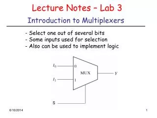
I . S=0. 0 . 2:1 Multiplexor. Z . I . 1 . S=1. S . Z . I . I . S . Z . Z = S' I 0 + S I 1. 1 . 0 . S. 0 . I . 0 . 0 . 0 . 0 . 0 . 1 . I . 0 . 0 . 1 . 0 . 1 . 0 . 1 . 0 . 1 . 0 . 1 . 1 . 0 . 1 . 0 . 0 . 0 . 1 . 0 . 1 . 1 . 1 . 1 . 0 . 1 . 1 .

E N D
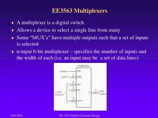
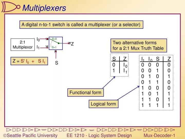
I S=0 0 2:1Multiplexor Z I 1 S=1 S Z I I S Z Z = S' I0 + S I1 1 0 S 0 I 0 0 0 0 0 1 I 0 0 1 0 1 0 1 0 1 0 1 1 0 1 0 0 0 1 0 1 1 1 1 0 1 1 1 1 1 Multiplexers A digital n-to-1 switch is called a multiplexer (or a selector) Two alternative forms for a 2:1 Mux Truth Table Functional form Logical form
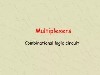
I 0 2:1 Z mux I 1 S I 0 I 1 4:1 Z I mux 2 I 3 S1 S0 I 0 I 1 I 2 I 3 8:1 Z I mux 4 I 5 I 6 I 7 S2 S1 S0 Multiplexers
VHDL Muxes LIBRARY ieee;USE ieee.std_logic_1164.all;ENTITY mux4to1 ISPORT( data : INSTD_LOGIC_VECTOR(3 downto 0); sel : INSTD_LOGIC_VECTOR(1 downto 0); z : OUTSTD_LOGIC);END mux4to1; Remember the IEEE library! Inputs: data[3..0],sel[1..0]Output: Z ARCHITECTURE behavior OF mux4to1 ISBEGINPROCESS(data,sel)BEGINCASE sel ISWHEN "00" => z <= data(0);WHEN "01" => z <= data(1);WHEN "10" => z <= data(2);WHEN "11" => z <= data(3);WHENothers=> z <= 0;END CASE;END PROCESS;END behavior; If Data or Sel change, output (Z) can change Set up as a CASE statement WHEN OTHERS – Use this even if there aren’t any others
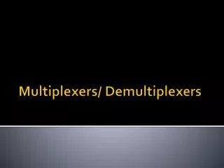
I0 0 8:1 4:1 I1 1 mux mux 2 I2 3 S S I3 2:1 1 0 0 Z I0 mux 0 I4 1 0 S I1 1 4:1 S I5 1 mux S0 I6 2 I2 0 I7 3 S S 1 0 0 I3 1 S 1 Z S1 S0 S0 S2 2 I4 0 3 S1 S0 I5 1 S S2 S1 S0 I6 0 I7 1 S S0 Cascading Muxes Large multiplexers can be implemented by cascaded smaller muxes Control signals S1 and S0 simultaneously choose one of I0-I3 and I4-I7 Control signal S2 chooses which of the upper or lower MUX's output to gate to Z Alternative 8:1 Mux Implementation
C B A F 1 0 0 0 0 1 0 1 0 0 1 0 1 2 8:1 F 0 1 0 1 0 3 MUX 0 4 0 1 1 0 0 5 1 0 0 0 1 6 1 0 1 0 1 7 S2 S1 S0 1 1 0 1 C B A 1 1 1 1 Using Muxes as logic blocks 2n-1:1 multiplexer can implement any function of n variables n-1 control variables; remaining variable is a data input to the mux F(C,B,A) = m0 + m2 + m6 + m7 1 Lookup Table 0 0 1
C B A F 0 0 0 0 0 0 0 1 0 1 4:1 A A 0 1 0 0 2 MUX 3 0 1 1 1 S1 S0 1 0 0 1 1 0 1 0 1 1 0 1 1 1 1 1 Optimized LUTs F(C,B,A) = m3 + m4+ m6 + m7 0 CB=00; F=0 0 F A CB=01; F=A A 1 CB=10; F=A’ C B CB=11; F=1 1 We can fit a function of n variables into a 2n-1:1 mux by using this trick (note: may require one inverter)
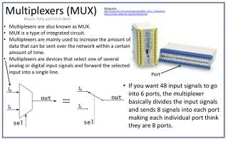
32 32 32 32 32 Using a multiplexor as a switch • Consider a computer system with CPU, memory, I/O devices, etc. • Each one needs to be able to communicate with the others… • Pros: • Conceptually simple Memory • Cons: • Lots of wires… • Each device needs separate output and input ports • 32-bit mux is a large device CPU 4:1 x 32bit Mux Disk 00 Control Example: Read a value from memory into CPU Keyboard
32 32 32 32 32 Using a Bus Bus – Bidirectional, Driven by one device at a time Memory A few (2-3) control lines to each device • Pros: • Much fewer wires • Simpler wiring • Expandable • One data port per device CPU Control Disk • Cons: • More complex electrically • Must manage bus Keyboard Critical issue: We’re connecting multiple outputs together. Bad Idea! Example: Read a value from memory into CPU
+5V +5V Smoke Happens… OK to connect one output to multiple inputs 1 0 Not OK to connect outputs together! Direct connection from power to ground – smoke!
5V In Out En In Out In Out In Out 0V Tri-State Inverter En=1 Enable High-Impedance (Hi-Z) state En=0 Modify an inverter… Tri-state Inverter
in0 sel0 in1 sel1 in2 sel2 out Using tri-state gates Goal: Connect three selectable inputs to a common output Whenever a select signal is asserted,that input is connected to the output Must make sure that there is always exactly one driver turned on!
O0 O0 O1 O0 = G • S; O1 = G • S G G O1 S S Demultiplexers Demultiplexer: One data input, n control inputs, 2n outputs Control inputs (called selects) - Binary index of output to which the input is connected Data input usually called “enable” (‘G’ or ‘E’) 1:2 Demultiplexer:
O0 O1 O2 O3 O4 O5 O6 O7 O0 O1 O2 O3 G G S1 S0 O0 = G • S2 • S1 • S0 O1 = G • S2 • S1 • S0 O2 = G • S2 • S1 • S0 O3 = G • S2 • S1 • S0 O4 = G • S2 • S1 • S0 O5 = G • S2 • S1 • S0 O6 = G • S2 • S1 • S0 O7 = G • S2 • S1 • S0 S2 S1 S0 O0 = G • S1 • S0 O1 = G • S1 • S0 O2 = G • S1 • S0 O3 = G • S1 • S0 Larger Demultiplexers/Decoders 1:8 Demultiplexer 3:8 Decoder 1:4 Demultiplexer 2:4 Decoder If we view the ‘G’ signal as an enable, then a demultiplexer simply decodes the binary select signal into a unary output signal Decoder • Decoder: • Enable=0 all outputs are 0 • Enable=1 output is unary representation of binary select input
Decoders In VHDL LIBRARY ieee;USE ieee.std_logic_1164.all;ENTITY Decoder2to4 ISPORT( s : INSTD_LOGIC_VECTOR(1 downto 0); en : INSTD_LOGIC; y : OUTSTD_LOGIC_VECTOR(3 downto 0)); END Decoder2to4; ARCHITECTURE logicfunc OF Decoder2to4 IS BEGIN PROCESS(s,en) BEGIN IF (en=‘1’) THEN CASE (s) IS WHEN “00” => y <= “0001”;WHEN “01” => y <= “0010”; WHEN “10” => y <= “0100”; WHEN “11” => y <= “1000”; WHEN OTHERS => y <= “0000”; END CASE; ELSE y <= “0000”; END IF; END PROCESS;END logicfunc; Sensitive to changes in s or en Only consider when en = ‘1’ Go through cases for all possible inputs If en = ‘0’, then output “0000”
w0 w1 w2 w3 w4 w5 w6 w7 y0 y1 y2 8-3Encoder Encoders Encoders are the opposite ofdecoders Binary output y[2..0] – Corresponds to the index of the input that is ‘1’ Unary input w[7..0] – exactly one of the eight inputs is ‘1’ For an 8-3 encoder, there should be 256 rows in the truth table Only rows with exactly one ‘1’ are valid Eight valid rows
w7 w6 w5 w4 w3 w2 w1 w0 y2 y1 y0 z 0 0 0 0 0 0 0 0 x x x 1 0 0 0 0 0 0 0 1 0 0 0 0 0 0 0 0 0 0 1x 0 0 1 0 0 0 0 0 0 1x x 0 1 0 0 0 0 0 0 1x x x 0 1 1 0 0 0 0 1x x x x 1 0 0 0 0 0 1x x x x x 1 0 1 0 0 1x x x x x x 1 1 0 0 1x x x x x x x 1 1 1 0 0 w0 w1 w2 w3 w4 w5 w6 w7 y0 y1 y2 0 1 1 6 0 1 0 Higher Priority 1 z 0 0 1 8-3PriorityEncoder 0 Priority Encoders What if more than one input to and encoder is ‘1’? Invalid input Output is undefined Priority Encoder: If more than one input is ‘1’, more significant bit has priority Add a ‘z’ output true when no inputs are ‘1’
VHDL Priority Encoder LIBRARY ieee;USE ieee.std_logic_1164.all;ENTITY Priority8 ISPORT( w : INSTD_LOGIC_VECTOR(7 downto 0); y : OUTSTD_LOGIC_VECTOR(2 downto 0); z : OUTSTD_LOGIC);END Priority8; Remember the IEEE library! Input: w[7..0]Outputs: y[2..0], Z ARCHITECTURE behavior OF Priority8 ISBEGINPROCESS(w)BEGIN IF (w(7)=‘1’) THEN y <= “111”; z <= ‘0’;ELSIF (w(6)=‘1’) THEN y <= “110”; z <= ‘0’;ELSIF (w(5)=‘1’) THEN y <= “101”; z <= ‘0’;ELSIF (w(4)=‘1’) THEN y <= “100”; z <= ‘0’;ELSIF (w(3)=‘1’) THEN y <= “011”; z <= ‘0’;ELSIF (w(2)=‘1’) THEN y <= “010”; z <= ‘0’;ELSIF (w(1)=‘1’) THEN y <= “001”; z <= ‘0’;ELSIF (w(0)=‘1’) THEN y <= “000”; z <= ‘0’;ELSE y <= “000”; z <= ‘1’;END IF;END PROCESS; END behavior; Case statement would require 256 rows… Use cascaded IFs