Download
1 / 18
180 likes | 329 Views
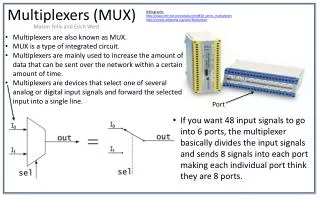
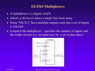
EE3563 Multiplexers. A multiplexer is a digital switch Allows a device to select a single line from many Some “MUX’s” have multiple outputs such that a set of inputs is selected

E N D
EE3563 Multiplexers • A multiplexer is a digital switch • Allows a device to select a single line from many • Some “MUX’s” have multiple outputs such that a set of inputs is selected • n-input b-bit multiplexer – specifies the number of inputs and the width of each (i.e. an input may be a set of data lines) EE 3563 Digital Systems Design
EE3563 Multiplexers • A mux may be used in digital communications • Voice requires 4 kHz of bandwidth (8 kilobits/sec) • If the total bandwidth is 64 kHz, then 16 voice users can talk “simultaneously” since the mux can switch them every 15.625μs • Since gate delays are on the order of 10ns, these speeds are easily achievable (and have been for many years) EE 3563 Digital Systems Design
EE3563 Multiplexers 250μs • 16-input 8-bit multiplexer . . 16 inputs . 16 users, 8 bits for each user There are 8, 16 input switches How many wires in? How many select lines are needed? EE 3563 Digital Systems Design
EE3563 Multiplexers • A mux may also be used to select registers in a microprocessor • We will study registers in Chapter 7, however, they can be thought of merely as cascaded flip-flops • A microprocessor may perform an “ADD” between two registers, the mux can select which two • As a side note, a microprocessor will use this technique to perform a variety of operations: ADD, SUB, AND, OR, NOT, XOR, etc. EE 3563 Digital Systems Design
. . 32 bit data . . . 32 bit data . . . 32 bit data . . . 32 bit data . M M U U X X R R R R B A e e e e g g g g i i i i s s s s t t t t e e e e r r r r EE3563 Multiplexers • Suppose there are 8 registers, 32 bits each (4 are shown) • What is the specification? (n=?, b=?) for each mux • How many select lines are needed for each mux? 32-bit data line A μP 32-bit data line B Select Lines EE 3563 Digital Systems Design
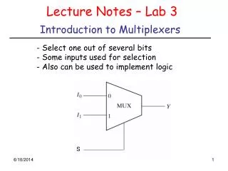
EE3563 Multiplexers • The 74x151 mux selects one of 8 inputs EE 3563 Digital Systems Design
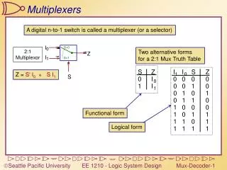
EE3563 Multiplexers • The truth table for a mux is very simple • What could we do to make the previous mux CMOS friendly? EE 3563 Digital Systems Design
EE3563 Multiplexers • Multiplexers can be cascaded as well, however, as the select signals drive more and more chips, fanout becomes a problem • For CMOS it is not the DC load that is the problem, but rather the capacitive load • What does that mean? • What can we do to solve the fanout problem? • What are the tradeoffs to these solutions? EE 3563 Digital Systems Design
EE3563 Demultiplexers • A demultiplexer (demux) performs the opposite function of the multiplexer • It takes 1 input and switch it between a number of outputs • Specified similarly to the multiplexer: b-bit n-output • For this general specification, how many select lines required? • A binary decoder, with an enable input, can be used as a demux • Truth Table for a 74x139 Decoder EE 3563 Digital Systems Design
EE3563 Parity Circuits • What is parity? • It is a simple “bit count” and is often used for error detection • There are two types: odd parity, even parity • Odd parity means that the output is one if an odd number of inputs are one • Even parity means that the output is 1 if an even number of inputs are one • Exclusive-OR (XOR) and Exclusive-NOR gates are essentially a parity checkers • Which one would be used for odd parity? EE 3563 Digital Systems Design
EE3563 Parity Circuits • What is parity? • It is a simple “bit count” and is often used for error detection • There are two types: odd parity, even parity • Odd parity means that the output is one if an odd number of inputs are one • Even parity means that the output is 1 if an even number of inputs are one • Exclusive-OR (XOR) and Exclusive-NOR gates are essentially a parity checkers • Which one would be used for odd parity? • XOR • Which one would be used for even parity? EE 3563 Digital Systems Design
EE3563 Exclusive-OR Implementations EE 3563 Digital Systems Design
A OUT IN Z B EE3563 Exclusive-OR Implementations Transmission Gate Implementation EE 3563 Digital Systems Design
EE3563 Exclusive-OR • We have discussed AND gates being enabled by a high input • OR gates are enabled by a low input • What are exclusive-OR gates enabled by? DATA DATA OUT OUT ENABLE ENABLE EE 3563 Digital Systems Design
EE3563 Exclusive-OR • We have discussed AND gates being enabled by a high input • OR gates are enabled by a low input • What are exclusive-OR gates enabled by? • It depends on whether we want an inverting output or a non-inverting output • A zero on the ENABLE input will enable a(n) _____ output? DATA DATA OUT OUT ENABLE ENABLE EE 3563 Digital Systems Design
EE3563 Parity Circuits • XOR gates can be cascaded to form multi-bit parity checkers • Both of these are odd parity circuits • Which one do you think has the lowest delay? EE 3563 Digital Systems Design
EE3563 Parity Circuits • 74x280 odd/even parity generator EE 3563 Digital Systems Design
EE3563 Parity Circuits • Parity Generation for an 8-bit Memory System EE 3563 Digital Systems Design