Download
1 / 35
410 likes | 1.09k Views
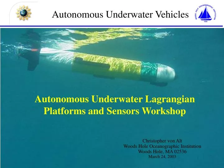
Autonomous Underwater Vehicles. Autonomous Underwater Lagrangian Platforms and Sensors Workshop. Christopher von Alt Woods Hole Oceanographic Institution Woods Hole, MA 02536 March 24, 2003. Outline. Background History Current Status The Future. WHOI Fast Fish (A. Bradley).

E N D
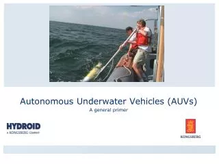
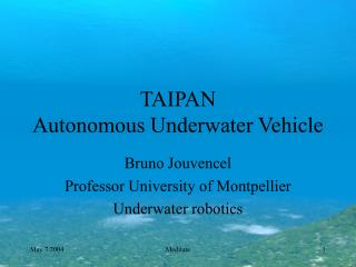
Autonomous Underwater Vehicles Autonomous Underwater Lagrangian Platforms and Sensors Workshop Christopher von Alt Woods Hole Oceanographic Institution Woods Hole, MA 02536 March 24, 2003
Outline Background History Current Status The Future WHOI Fast Fish (A. Bradley)
Autonomous Under Vehicles • Driven by a propulsion system • Controlled and piloted by an onboard computer • Maneuverable in three dimensions • Support spatial and time series measurements • Normally provide superior quality data • Support multiple vehicle operations • Can insure adequate spatial and temporal sampling • Support investigations of spatial and temporal coherence
Comparison with other Lagrangian Platforms • Benefits • Control of survey • Adequate power for most sensors • Adequate power to continuously sample • Drawbacks • Limited endurance – 8 - 50 hours • Higher platform costs • Lower number of platforms – less access
Benefits of AUV’sWater column measurements • Stop and float – requires ballast control • Actively loiter • Constant altitude above the bottom • Constant pressure or layer of interest • Sea saw or saw tooth sample pattern • Seafloor surveys – acoustic or optical
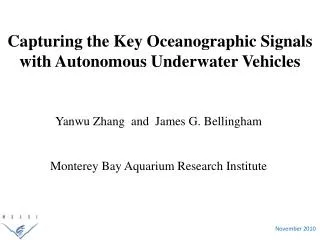
Time series measurements Over 500 km mapped in 100 hours.
transponders PHILLS OVERFLIGHT San Luis Bay – Spatial Time Series REMUS transect M. Moline California Polytechnic State University
Fluorometer OBS (on back) Biolum intake Bioluminescence Sensor Developed by Mark Moline at Cal Poly, Cyril Johnson, Jim Case at UCSB
6.75E+11 a 8.10E+10 6.75E+11 b 8.10E+10 Bioluminescence (photons L-1) 1.2E+11 c Depth (m) 3.0E+9 3.0 3.0 3.0 3.0 3.4E+9 d 13.0 13.0 13.0 13.0 5.8E+10 0.0 1.5 Range (km) San Luis Bay – Weekly Deployments . M. Moline California Polytechnic State University
Acoustic range of transponders REMUS transect Dead Reckoning Zone 0.0 kilometers 20.0 Monterey Bay – Spatial Time Series . M. Moline California Polytechnic State University
15 Temperature (C) 10 33.65 Salinity (ppt) 33.45 3.0E+11 Biolum (photons L-1) Depth (m) 3.0 3.0 3.0 3.0 3.0 2.0E+08 3.0 Fluor (Volts) 40.0 40.0 40.0 40.0 40.0 0.0 0.08 Optical Backscatter (Volts) 0.0 Range Offshore (km) 0.0 20.0 August 20, 2002 M. Moline California Polytechnic State University
Developed in the early 90’s Operational ’94 Six vehicles developed Characteristics Displacement: 160 kg Survey speed: 1.5 m/s Max depth: 6 km Endurance 6 hours Notable missions AOSN missions & docking Mission depth 1.4 km Mission duration 3 hours Odyssey MIT Sea Grant
Developed in the early 90’s Operational ’94 Completed 80 science dives Characteristics Displacement: 680 kg Survey speed: 0.75 m/s Max depth: 5 km Endurance 34 hours Notable mission 1996 Mission depth 2.2 km Mission duration 30 hours ABE - Autonomous Benthic Explorer
International Submarine Ltd Thesues • Developed early 90’s • Operational 94 • Characteristics • Displacement: 8,600 kg • Survey speed: 2 m/s • Max depth: 1 km • Endurance 100 hours • Most notable mission 1996 • Deployed 190 km of fiber optic cable on the seafloor (500 m) under ice • Mission distance 365 km • Mission duration 50 hours
Naval Oceanographic Office UUV Program • Draper UUVs • WHOI Tracking System • Penn State- Seahorse • Semi-Autonomous Mapping System • UUV Fest
Developed early 90’s Operational 98 Characteristics Displacement: 1,700 kg Survey speed: 1.5 m/s Max depth: 1.6 km Endurance 144 hours Notable information 271missions/750 hours/3596 km Deepest mission 1 km Longest mission 50 hours Southampton Oceanographic Center Autosub Offered 2.6 m pounds in 1998
Developed late 90’s Operational 00 Characteristics Displacement: 8,600 kg Survey speed: 2 m/s Max depth: 3 km Endurance 40 hours Most notable missions System mapped 17,702 km Mission depth 3 km Commercial Services C&C Technologies, Inc. Kongsberg Simrad HUGIN Vehicle - Norway
Dr Jay Farrell Adaptive SamplingAdaptive Mission Planner (AMP) • The AMP is a separate ‘brain’ installed on the vehicle • AMP has the ability to take control of the vehicle and provide it with external navigation and control commands • Vehicle takes over if AMP tells it to do something dangerous • During normal operations, the vehicle • Executes a pre-programmed mission • Navigates from waypoint to waypoint • AMP • On board algorithm adaptively modifies plan based on inputs received during the mission from its sensors
Dr Jay Farrell Conventional Appraoch Conc --> 0 min Time ( as the UUV conducts its mission) ---> 24 min
Dr Jay Farrell Adaptive Plume Following Spatial Map Plume Tracing
Automated Target DetectionHuman in the loop 4. Acoustic modem on vehicle transfers data to HSV-1 via an RF link 3. Vehicle CPU Assembles message with target snippet 1. Vehicle surveys area with sidescan sonar Modem Buoy With RF Link 2. On Board CAD/CAC autonomously scans sonar files and identifies targets HSV 1 5. Target data is analyzed on laptop
Redirection of Reacquisition Vehicle Image snippets sent back, displayed Reacquisition vehicle is directed to survey targets with high scores from CAD/CAC The survey mission is sent to the vehicle via the acoustic modem and RF link - the vehicle interprets this message and performs the mission. Operator creates redirection survey on REMUS VIP
“Human in the loop” Redirection Mission with two vehicles in the water • SCM vehicle performs survey • Reacquire vehicle loiters • CAD/CAC system passes targets to HSV • Reacquire vehicle receives new mission and exits loiter location • SCM vehicle continues the survey seeking another target
REMUS 6000 • Stand-alone 6 km rated self contained system • Transportable - one ISO container • Productive – 3 – 10 times current survey rates • Affordable - $1 M/vehicle • Multiple vehicle operations (Two vehicles may be stored in one container.)
Mission 13 12nm Redirect Rim - 2,250 m Base - 3,875 m Depth 1,625 m Transect 20,000 m Slope 4.6 deg Vehicle Transect
Descent Down the North Kaibab Trail Rim 2,512 m Colorado River 739 m Depth 1,773 m Trail Length 22,000 m Slope 4.6 deg. Bright angel point
Benefits of AUV’sShip based deep water operations • Increase survey speeds • Precise feature following • Acoustic communication • Uplink sensor data • Redirect mission or reconfigure sensors • Superior data quality • Portability • Cost effective 40% to 60% savings
C&C Technologies, Inc. • Yearly support costs $14 million • Ship, software engineers, consumables, parts and depreciation. • Adequate utilization main problem not enough business to support the capabilities of the system. • Offering 50 days of AUV time per year for $60k/day