Download
1 / 24
310 likes | 816 Views
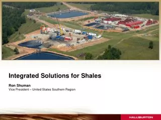
Seismic attributes of the Barnett and Bakken shales. Bode Omoboya 16 th May, 2013. Introduction Bakken Shale Case Study Barnett Shale Case Study Other Forward Modeling Projects. Bakken Shale Quick Facts. VTI Anisotropy. Isotropic or HTI Anisotropy Due Open Vertical Fractures.

E N D
Seismic attributes of the Barnett and Bakken shales Bode Omoboya 16th May, 2013 Introduction Bakken Shale Case Study Barnett Shale Case Study Other Forward Modeling Projects
Bakken Shale Quick Facts VTI Anisotropy Isotropic or HTI Anisotropy Due Open Vertical Fractures VTI Anisotropy Most oil in the Bakken petroleum system resides in open fractures in the Middle Member (Pitman et al, 2001). Source: USGS
Bakken Shale – Core Samples and Well Logs Upper Shale MD= 9100 ft Middle Member MD= 9250 ft Lower Shale Well: NELSON Core Image from NDIC
Bakken Shale – Shale Volume 200 ft. Interval 80% Vsh 1000 ft. Interval 40% – 60% Vsh Steiber, 1970 Data Courtesy of Hess Corporation
Bakken Shale – Non-Hyperbolic Moveout t=700 ms X/D=1 4500ft (offset) t=1800 ms X= 15000 ft X= 0 ft V=16000ft/s V=3000ft/s from Core = 0.341 from Seismic ≈ 0.32 Jones and Wang, 1981
Bakken Shale – Forward Modeling Project After Post-stack Migration Before Post-stack Migration Model C1 Physical modeling of anisotropic domains: Ultrasonic imaging of laser-etched fractures in glass (Geophysics, 2013 ) Robert. R. Stewart Nikolay Dyaur Bode Omoboya J.J.S de Figueiredo Mark Willis Samik Sil
Bakken Shale – Forward Modeling Project Model C3 Model C10 Model C9 “BAKKEN MODEL” Schematic of NMO eta scan experiments on glass models
Bakken Shale – Forward Modeling Project 𝞰= 0.3 𝞰= -0.3 𝞰= 0.3 𝞰= -0.3 Model C10 VTI Model Model C3 Max 𝞰 = 0.0 Blank Model Model C9 Azimuth 0 Max 𝞰 = 0.14 VTI+HTI+VTI Model C9 Azimuth 0 t = 350 ms t = 350 ms Model C9 Azimuth 45 Model C10 Max 𝞰 = 0.23 VTI Model Model C9 Azimuth 45 Max 𝞰 = 0.08 VTI+HTI+VTI t = 350 ms Model C9 Azimuth 90 Model C3 Blank Model t = 350 ms Model C9 Azimuth 90 Max 𝞰 = -0.06 VTI+HTI+VTI t = 350 ms
Barnett Shale Quick Facts N-S structural cross section through the Newark Field in the Fort Worth Basin. Modified after Burna and Smosna, 2011
Barnett Shale – Top Ellenberger – Maximum Curvature Attribute Well Y Well X Data Courtesy of Marathon Oil
Barnett Shale – CDP Gathers after Time Processing and Migration
Barnett Shale – Migrated Stack + FXY Decon t = 0s t = 1.5s
Barnett Shale – Residual eta (h) Volume h = -0.2 t = 0s t = 1.5s h = 0.2
P-Impedance Volume t = 0.55ms Base Marble Falls Top Barnett Top Ellenberger t = 0.85ms
Density Volume t = 0.55ms Base Marble Falls Top Barnett Top Ellenberger t = 0.85ms
Mu-Rho Volume t = 0.55ms Base Marble Falls Top Barnett Top Ellenberger t = 0.85ms
Barnett Shale – Forward Modeling Project Experimental study of the influence of fluids on seismic azimuthal anisotropy. (Geophysical Prospecting, 2013, submitted, under review) Bode Omoboya Emrah Pacal J.J.S de Figueiredo Nikolay Dyaur Robert. R. Stewart • Constituent Materials: • Resin • Plexiglass (polycarbonate) • Copper tubes
Barnett Shale – Forward Modeling Project Vs (Z) m/s
Barnett Shale – Forward Modeling Project C11 C33 C13 C44 C55 C11 C33 C13 C44 C55
Forward Modeling Examples: Source Frequency VS Anisotropy ɛ = Hudson, 1981 Model M1 Reference Model Model M2 Crack Density = 4.5 % Model M3 Crack Density = 4.0 % Shear wave anisotropy from aligned inclusions: ultrasonic frequency dependence of velocity and attenuation (Geophysical Journal International, 2013) J.J.S de Figueiredo Nikolay Dyaur Bode Omoboya Robert. R. Stewart
Forward Modeling Examples: Source Frequency VS Anisotropy Thomsen, 1986
Acknowledgement • Dr. Steve Peterson – Marathon Oil • Michelle Simon – Hess Corporation • Dr. Edip Baysal – Paradigm • Schlumberger (For VISTA Processing Software)