Download

1 / 39
390 likes | 402 Views
PowerPC 604 Superscalar Microprocessor. IBM, Motorola, Apple. PPC604e Overview. RISC PowerPC family PowerPC architecture : 32-bit effective (logical) addresses,

E N D
PowerPC 604 Superscalar Microprocessor IBM, Motorola, Apple
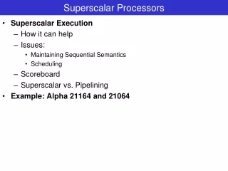
PPC604e Overview • RISC PowerPC family • PowerPC architecture : • 32-bit effective (logical) addresses, • 8, 16, and 32 bits integer data types, and floating-point data types of 32 and 64 bits (single- and double-precision, respectively). • A superscalar processor : can issue four instructions • Up to seven instructions can execute in parallel.
Overview: 604e has 7 units • The 604e has seven parallel – independent execution units • Floating-point unit (FPU) • Branch processing unit (BPU) • Condition register unit (CRU) • Load/store unit (LSU) • Three integer units (IUs): • — Two single-cycle integer units (SCIUs) • — One multiple-cycle integer unit (MCIU)
Three-stage pipelined floating-point unit (FPU) • Fully IEEE 754 compliant FPU • Supports non-IEEE mode for time-critical operations • Fully pipelined, single-pass double-precision design • Two-entry reservation station to minimize stalls • Thirty-two 64-bit FPRs for single- or double-precision operands
BPU & CRU • BPU Branch Processing Unit with dynamic branch prediction • Two-entry reservation station • Out-of-order execution through two branches • 64-entry fully-associative branch target address cache (BTAC), 512-entry branch history table (BHT) • Two bits per entry predictions • Condition register unit (CRU) • Two-entry reservation station
Branch History Table (BHT)Table of predictors • Each branch given predictor • BHT is table of “Predictors” • Could be 1-bit or more • Indexed by PC address of Branch • most schemes use at least 2 bit predictors • Performance = ƒ(accuracy, cost of misprediction) • Misprediction Flush Reorder Buffer • In Fetch state of branch: • Use Predictor to make prediction • When branch completes • Update corresponding Predictor Predictor 0 Branch PC Predictor 1 Predictor 7
Branch PC Predicted PC BTB: Branch Address at Same Time as Prediction • Branch Target Buffer (BTB): Address of branch index to get prediction AND branch address (if taken) PC of instruction FETCH Yes: instruction is branch and use predicted PC as next PC =? prediction state bits No: branch not predicted, proceed normally (Next PC = PC+4) Only predicted taken branches and jumps held in BTB Next PC determined before branch fetched and decoded later: check prediction, if wrong kill instruction, update BPb
PowerPC604 Pipeline overview • Instruction fetch (IF) — loads decode queue (DEQ) with instructions from I - cache and determines next instruction address • Instruction decode (ID)— time-critical decoding on instructions in dispatch queue (DISQ). • Instruction dispatch (DS)— • up to 4 instructions dispatched – max – in order • one per functional unit • non- time-critical instructions decoding. • determines when instruction can be dispatched to EX Units • At end of DS, instructions and their operands are latched into the execution input latches or into unit’s reservation station. • Rename registers and reorder buffer entries allocated
Execute (E), Complete (C), Writeback • • Execute (E) • instruction flow split among six execution units. Instructions enter execute from dispatch or reservation station. • results written into rename buffer entry ; notifies complete stage • • Complete (C) • ensures correct machine state maintained ; monitors instructions in complete and execute stages. • Instructions removed from reorder buffer (ROB) when complete • Results written back from rename buffers to register at complete or writeback • • Writeback (W) writes back results from rename buffers not written back during complete
Branch PC Predicted PC BTB: Branch Address at Same Time as Prediction • Branch Target Buffer (BTB): Address of branch index to get prediction AND branch address (if taken) PC of instruction FETCH Yes: instruction is branch and use predicted PC as next PC =? prediction state bits No: branch not predicted, proceed normally (Next PC = PC+4) Only predicted taken branches and jumps held in BTB Next PC determined before branch fetched and decoded later: check prediction, if wrong kill instruction, update BPb
Example 2 : Branch Taken with BTAC hit No branch penalty; 4 OR is from target stream Cycle 2: instructions 4 – 7 fetched from Target based on address from BTAC HIT Cycle 5: inst. 2 -3 wait for LD to retire (WB) & retire with it
Example 2: Branch taken with BTAC HIT No penalty
Ex 4: Branch taken, BTAC Miss, correct at Decode stage One clock penalty, to fetch target group (2,3,4,5) Correction at Decode includes branch on CR (flags), LR
Ex 5: Branch taken, BTAC Miss, correct at Dispatch stage - 2 clock branch penalty
Example 6: Branch taken, BTAC Miss, correct at Execute --- 3 clock penalty
Class Example – real dependencies 1 ADD R1, R2, R3 ; R1 = R2 + R3 2 ADD R2, R1, R4 3 OR R3, R1, R4 4 SUB R3, R2, R3 5 FMUL F7, F5, F6 6 FSUB F8, F10, F7 7 AND R4, R1, R3
Pipeline Details: Fetch Stage • Fetches instructions from I cache and loads decode queue (DEQ) • Determines address of next instruction to be fetched. • Keeps queue supplied with instructions for dispatch • Instructions fetched from I cache in groups of four, from a cache block • If only two instructions remain in the cache block, only two instructions are fetched.
next instruction fetch address: • Each stage offers candidate address to be fetched, latest stage has highest priority • As a block is prefetched, branch target address cache (BTAC) and branch history table (BHT) searched with fetch address. • If address is in BTAC, next instruction fetched from that address • DECODE may indicate, based on BHT or an unconditional branch decode, that earlier BTAC prediction was incorrect • BPU can indicate that a previous branch prediction, from the BTAC or DECODE was incorrect
Decode Stage • Handles time-critical decoding of instructions in instruction buffer. • Contains four-instruction buffer (DEQ); shifts one or two pairs of instructions into dispatch buffer as space becomes available. • Branch correction predicts branches whose target is taken from the CTR or LR. Occurs if no CTR or LR updates are pending.
Dispatch Stage • non–time-critical decoding of instructions supplied by decode • determines which instructions can be dispatched • source operands read from register file and dispatched to execute units • dispatched instructions and their operands latched into reservation stations or execution unit input latches. • Dispatched Instructions issued a position in 16-entry completion buffer • Rename Buffer allocated to instruction if needed
Execute Stage • Instruction passed to appropriate execution unit after fetch, decode, and dispatch. EX units have different latencies • Floating-point unit has fully pipelined, three-stage execution unit • EX units write results into appropriate rename buffer & notifies complete stage
Branch Mispredict / Exceptions ? • What if a branch instruction was mispredicted in an earlier Stage ? • Instructions from mispredicted path flushed • Fetching resumes at the correct address. • If an instruction causes an exception, the execution unit reports the exception to the complete stage and continues executing instructions
CompleteStage • maintains correct architectural machine state. • As instruction finish EX, their status is recorded in completion buffer (FIFO) entry. • entries examined in order in which instructions dispatched. • Retains program order, ensures instructions completed in order • four entries examined during each cycle for writeback • completion buffer is used to ensure a precise exception model. .
Write-Back Stage • Write back results from rename buffers not written back by the complete stage. • Each rename buffers has two read ports for write-back, corresponding to the two ports provided for write-back for the GPRs, FPRs, and CR. • Two results can be copied from the write-back buffers to registers per clock cycle.