Download
1 / 41
480 likes | 780 Views
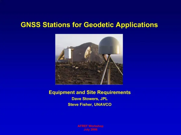
Permanent GPS Stations in Israel as Basis for Updated Geodetic Network Gilad Even-Tzur Faculty of Civil and Environmental Engineering Mapping and Geo-Information Engineering Technion, Haifa 32000, Israel Moshe Rozenblum, Einat Salomon Survey of Israel

E N D
Permanent GPS Stations in Israel as Basis for Updated Geodetic Network Gilad Even-Tzur Faculty of Civil and Environmental Engineering Mapping and Geo-Information Engineering Technion, Haifa 32000, Israel Moshe Rozenblum, Einat Salomon Survey of Israel 1 Lincoln St. Tel-Aviv 65220, Israel
Permanent GPS Stations in Israel, Sept. 2005 AREL DSEA SLOM YRCM NRIF 17 Stations Receivers: 11 Ashtech Z-XII 5 Leica SR530 1 Trimble 5700 Antennas: 9 Ashtech DM 5 Leica DM 2 Topcon CR4 1 Trimble DM
Permanent GPS stations in Israel, Sept. 2005 AREL DSEA SLOM YRCM NRIF 10 stations are situated on stable roof tops NRIF
Permanent GPS Stations in Israel, Sept. 2005 AREL DSEA SLOM YRCM NRIF 7 stations have geodynamic monuments LHAV
The Control Center The GPS receivers are connected to a control center, equipped with master and backup servers, through frame relay connections.
The GPS Data Flow AREL DSEA SLOM YRCM NRIF 5 sec sampling rate Data is downloaded in real time The RINEX data is gathered into 1-hour interval files and posted on the internet
Operation Manager Software The network is controlled by the RTD software. It is based on epoch-by-epoch technology, which enables monitoring any changes in the station coordinates due to deformation and lost qualities.
Permanent GPS Stations in Israel, Sept. 2005 AREL DSEA SLOM YRCM NRIF RAMO is the official IGS station in Israel The data is processed at SOPAC The data from RAMO and DRAG is also processed at GIBS (GPS-Informations- und Beobachtungssystem)
The Permanent GPS Stations in Israel are called: APN Active Permanent Network AREL DSEA SLOM YRCM NRIF Free 30 sec sampling rate data is available at: ftp://212.179.112.235
The APN Network AREL DSEA SLOM YRCM NRIF Until recently, the APN network was mainly used for geodetic and geophysical research. The APN was used less for surveying purposes: - Short sessions - OTF ambiguity resolution used - Lack of transformation between WGS84 and ITM
VRS - Virtual Reference Station Economically and practically, there is no need to increase the number of permanent GPS stations in Israel. In order to enable GPS surveying over the entire state of Israel with direct connection to the permanent GPS network, VRS technology is applied. The VRS is produced by the GEO++ software
Advantages of Using the APN • Uniformity • Accuracy • Reliability • Simplicity ► In the near future an RTK option will be added to the APN network
Datum Definition ► Geodetic datum is a set of parameters and control points used to: ● Define the size and shape of the earth. ● Define the origin and orientation of the coordinate systems used to map the earth. ►Geodetic datums range from flat-earth models used for plane surveying to complex models used for international applications. ►The datum is the basis for a plane-coordinate system.
Datum Definition (continuance) ► GPS positions and vectors are referenced in the WGS-84 datum ► The Israeli coordinate systemis referenced in the GRS-80 reference ellipsoid with geodetic projection called: ITM - Israel Transverse Mercator
Datum Transformation Shifts Scale Rotations Transformation parameters describe the relations between two different datum systems. 7 Parameter transformation:
Datum Transformation (continuance) The set of transformation parameters is determined by a least-squares solution:
The Plane Coordinates of the APN Points ►Each point from the APN network was connected by GPS observations to the nearest 1st order control points. ►A local datum transformation was calculated in order to assign plane coordinates to each permanent GPS station. The accuracy of the coordinates is equivalent to the accuracy of the classical 1st order control network (~10cm)
Permanent GPS Network A permanent GPS-based network is obviously more accurate, reliable and homogenous than a classical network. Permanent GPS Network Supreme Network
New Datum for APN A set of coordinates that was valid for GPS day 275 of the year 2004 (October 1st, 2004) in the ITRF2000 coordinate system was set as the fixed coordinates set for the permanent GPS stations This set of coordinates defined a new datum for APN, called IGD05 Israel Geodetic Datum 2005
Scale Network: Residual: 50km 5cm Horizontal residuals resulting from the seven parameters transformation between the ITRF2000 (IGD05) datum and the Israel Grid datum
New Datum for Israel Grid A new set of plane coordinateswere adopted for the APN points. The new coordinates defined actually new datum for the Israeli Grid called: IG05 Israel Grid 2005 The adopted plane coordinates is a result of similarity transformation between two datums (IGD05 and IG05) which supplied practically zero residuals in the least-squares process.
Official 7 Parameters Transformation Calculate official 7 parameter transformation between the two systems IGD05 IG05
A flow chart for calculating new control points in IG05 coordinate system
Measuring methods for establish new control point 1. Relative to APN station 2. Relative to VRS 3. Relative to base station 4. Geodetic network
Field Work Guidelines ► Two independent Observation sessions ► Observation sessions of at least 10 min ► Time duration between two sessions of at least 60 min
1. Measuring relative to APN station First session: 10min 10min 10min 10km TELA 10min
1. Measuring relative to APN station Second session: 10min 10min TELA 10min Time duration between sessions – 60 min
2. Measuring relative to VRS First session: 10min 5km 10min 10min VRS1 10min
2. Measuring relative to VRS Second session: 10min 10min VRS1 10min VRS2 VRS3 The distance between two VRS should be at least 120m Time duration between sessions – 60 min
2. Measuring relative to VRS VRS1 VRS2 VRS3 Measured vectors:
3. Measuring relative to base station IGD05 ► Connect the base station toIGD05 system 10km 90min BASE IGD05
3. Measuring relative to base station IGD05 ►Measuring new control points First Session: 10min 10min 10min BASE 10min IGD05
3. Measuring relative to base station ILGD05 ►Measuring new control points Second Session: 10min 10min BASE 10min ILGD05 Time duration between sessions – 60 min
4. Measuring Geodetic Network Assume work with 3 receivers IGD05 1 • Sessions of at least 10 min • Each new point should be measured in two independent sessions 2 3 4 IGD05
The Geodetic-Geodynamic Network (G1) ►Includes 160 points that homogeneously cover the state of Israel ►The location of the points was determined mainly according to geological considerations ► The points were built according to very high technical specifications, to ensure their geotechnical stability
The goal of the Geodetic-Geodynamic Network ►A potential geodetic network for monitoring deformations in primary and secondary known faults ►Serves as the major geodetic control network of Israel
The Measurement Campaigns ►During 1996 the G1 network was measured for the first time (Blue circles and Red squares) ►The second campaign was held in 2002 ► Only100 points were measured (Blue circles) ► 5 new points were fixed in the northern part of the network (Yellow circles ) ► 11 continuous permanent GPS stationswere operated (Green triangles) ► the accuracy of the points is better than 1cm
The G2 Network ►Abut 1000 points that organized in closed loops ►Most of the points are BMs from the Israeli vertical control network ► The points were measured during long period and not as one campaign ►The network accuracy is not homogeneous and not satisfactory (~5cm)
Vertical Control ►Survey of Israel (SOI) decided that the future vertical control in Israel will be based on ellipsoidal heights instead of orthometric heights ►SOI will support and maintain spatial geodetic network which will serve as horizontal and vertical control ►The APN and G1 will be used as basis for ellipsoidal vertical control ►Undulation model will be used to convert ellipsoidal heights to orthometric heights