Download
1 / 40
700 likes | 2.62k Views
Process Integrated Membrane Separation - with Application to the Removal of CO 2 from Natural Gas Hilde K. Engelien. 22. March 2004 Department of Chemical Engineering, NTNU. Definition of Given Title. Process integrated membranes: Membranes integrated into a process.

E N D
Process Integrated Membrane Separation - with Application to the Removal of CO2 from Natural GasHilde K. Engelien 22. March 2004 Department of Chemical Engineering, NTNU
Definition of Given Title Process integrated membranes: • Membranes integrated into a process. • Process integration techniques (process synthesis, modelling & optimisation). CO2 removal from natural gas: • Have mainly looked at natural gas sweetening. • Other applications exists.
Overview of Presentation • Membranes • Principles of separation • Material selection • Types of membrane modules • Membrane separation for CO2 removal from natural gas • Applications for CO2 removal • Natural gas • Advantages/disadvantages • Current solutions & some industrial examples • Process integration • Future trends & developments • Concluding Remarks
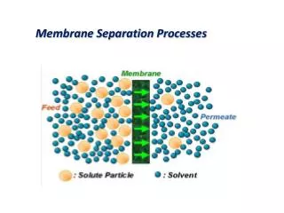
Membrane module Feed Retentate Permeate Principles of Membrane Separation Phase 1 Phase 2 (Feed) (Permeate) Membrane - a physical barrier from semi-permeable material that allows some component to pass through while others are held back. Microfiltration Ultrafiltration Reverse Osmosis Molecular sieving Gas separation Membrane contactors Pervaporation Driving force (C, P, T, E) Flux Selectivity
Different Membrane Structures(Selective layer) Porous membrane Non-porous membrane Carrier membranes Size Diffusion & solubility Affinity Ref: Mulder, Basic principles of separation technology) (microfiltration/ultrafiltration) (gas separation/pervaporation) (gases/liquids)
Typical Membrane Structures(Gas Separation) Composite membranes: • thin selective layer of one type polymer • mounted on asymmetric membrane - support Asymmetric membranes: • very thin non-porous layer - selective • thick, highly porous layer - mechanical support Selective layer Nonporous layer (selectivity) Asymmetric membrane Porous layer (stability) Composite membrane structure (two types of materials) Asymmetric membrane structure (one type of material) Ref. Dortmundt, 1999
Membranes - Material Selection Polymers: most common Inorganic: more stable hybrid Polymer: poly(ethene) Monomer: ethene Ref.: www.btinternet.com/~chemistry.diagrams/polymer.htm
Different Types of Membrane Modules • Two main categories for industrial applications: • Spiral wound modules • Hollow fibre modules Ref.: Filtration Solutions Inc.
Different Types of Membrane Modules • Two main categories for industrial applications: • Spiral wound modules • Hollow fibre modules Cross section of hollow fibre Ref.: Aquilo Gas Separation
Applications for CO2 Removal • Separation of CO2 from gas streams are required in: • Purification of natural gas (gas sweetening). • Separation of CO2 in enhanced oil recovery processes (EOR). • Removal of CO2 from flue gas. • Removal of CO2 from biogas. • Reasons for sour gas sweetening ? • Impurities (CO2, H2S, H2O) • Increase heating value of natural gas - pipeline quality gas. • Reduce corrosion. • Prevention of SO2 pollution (formed during combustion of natural gas). • Methods used in gas sweetening (removal of CO2, H2S) • Absorption process using amine (conventional). • Cryogenic distillation. • Membranes. • Hybrid process where membrane is integrated with absorption unit.
Natural Gas • Natural gas: Mainly methane (CH4), ethane, propane, butane. • Impurities: H2O, CO2, N2 and H2S. • Natural gas treatment is the largest application of industrial gas separation. Membrane processes have < 1% of this market large potentials ! (Baker, 2002) • “Disposal”: Compression & re-injection of CO2 in reservoir . Ref.: Australian Petroleum Cooperative Research Centre
Typical Natural Gas Plant- Possible Membrane Applications Ref.: UOP
l CH4 + CO2 CO2 P CO2 Separation Using Membranes • Mechanism of separation: diffusion through a non-porous membrane • A pressure driven process - the driving forceis the partial pressure difference of the gases in the feed and permeate. • Selectivity - separation factor, (typical selectivity for CO2/CH4 is 5-30) • Permeability = solubility (k) x diffusivity (D) • Either high selectivity or high permeability - use highly selective thin membranes. • Commercial membranes: polymer based (cellulose acetate) • Selective removal of fast permeating gases from slow permeating gases. • The solution-diffusion process can be approximated by Fick’s law:
CO2 Removal from Natural GasCurrent Membrane Solutions • Membranes (Baker, 2002): • 8-9 polymer materials used for 90 % of total gas separation membranes. • Several hundred new polymers reported (academia/patents) in the last few years. Problem: maintaining properties during real operation. • Most gas separation modules are hollow-fibre modules. • Three markets: • Low gas volumes (e.g. treatment of offgas) - better than conventional amine absorption units. • Moderate gas volumes - competitive with amine systems. • Higher volumes - not competitive with current amine systems. Problem: low selectivity and flux. • Hybrid solution with conventional amine absorption technology. • Feed treatment - extend membrane life (condensing liquids, particles causing blockage and well additives can harm the membrane).
CO2 Separation Using Membranes: Advantages & Disadvantages Advantages (compared with absorption units): • Simpler process solutions • Smaller & lighter systems (offshore) • Cleaner • Less chemical additives • Lower energy consumption • Simultaneous removal of CO2, H2S and water vapour • No fire or explosion hazards • Less maintenance • Lower capital and operating costs (small to medium scale) • Ability to treat gas at wellhead Disadvantages: • Low selectivity & flux - large scale systems not economically viable (yet). • Thermal stability of polymer membranes. • Degradation & lifetime of membrane. • Unmature technology (in industrial terms, compared with existing solutions) Abetter environmental solution than conventional absorption units
Natural Gas Processing PlantQadirpur, Pakistan • In 1999: Largest membrane based natural gas plant in the world (Dortmundt, UOP, 1999). • Design: 265 MMSCFD natural gas at 59 bar. • CO2 content is reduced from 6.5 % to less than 2 % using a cellulose acetate membrane. • Feed treatment & feed heaters. • Also designed for gas dehydration. • Plant processes all available gas. • Plans for expansion to 400 MMSCFD.
Membrane plant, Qadirpur, Pakistan (Dortmundt, UOP, 1999)
Examples of Membranes In Gas Industry Plants using membranes for CO2 removal: • Kadanwari, Pakistan - 2 stage unit for treatment of 210 MMSCFD gas at 90 bars • Taiwan (1999) - 30 MMSCFD at 42 bar. • EOR facility, Mexico - processes 120 MMSCFD gas containing 70 % CO2 • Slalm & Tarek, Egypt - 3 two-stage units each treating 100 MMSCFD natural gas at 65 bar. • Texas, USA - 30 MMSCFD of gas containing 30% CO” at 42 bar. Companies with membranes for CO2 removal: • NATCO Group (Cyanara membranes) • Aker Kværner Process Systems • Air Liquid • UOP
Process Integrated Membrane:Membrane Gas/Liquid Contactors • Process integrated membrane and absorption unit (developed by Kværner Process Systems). • Membrane acts as barrier & surface area. • Increased mass transfer area. • Used for natural gas treatment, dehydration and removal of CO2 from offgas. Ref.: Aker Kværner Process Systems • There are several tests sites for this system (Falk-Pedersen) : • Large laboratory unit at SINTEF. • Large scale pilot unit at Kårstø (exhaust gas treatment from gas engine) • Pilot unit at gas terminal in Scotland - testing different membranes.
Membrane Gas/Liquid Contactors Benefits: • Reduction of size and weight (important offshore). • Wide range of liquid and gas flows (separation of gas/liquid phase). • Lower capital costs compared with alternative schemes. • Reduction in energy (if membranes are integrated with the stripping unit). • Reduction in solvent losses. • No entrainment, flooding or channelling. • Performance is insensitive to motion. Santos Gas Plant, Queensland, Australia • Australia's largest gas producer. • Novel polymide membrane facility for CO2 removal (installed Dec. 2003). • Uses the gas/liquid contactor. • Problem: benzene/toluene/xylene in gas stream - a dewpoint control unit is installed to ensure that BTX are at acceptable levels.
Process Integration for Membrane Applications • Design. • Modelling & optimisation. • Superstructure approach for optimisation. Process synthesis andoptimisation methods are important for development of efficient membrane structures for specific separation tasks.
Process Integration Usedin Membrane Applications • Design. • Modelling & optimisation. • Superstructure approach for optimisation. • Design decisions for membrane systems: • Operating conditions (temperature, pressure, flow). • Module configuration (parallel, series, single stage, multiple stage, recyle). • Membrane material (organic, inorganic, mixed, …). Single stage scheme Two-step scheme Two-stage scheme
Process Integration for Membrane Applications • Design. • Modelling & optimisation. • Superstructure approach for optimisation. • Modelling of membrane designs for gas (Pettersen, Lien, 1993, 1994, 1995) : • Parametric study. • Algebraic model (analogous with counter-current heat exchanger). Looked at single stage and multiple stages, effects of recycle and bypass configurations. • Classification modules - suitable for recovery of fast or slow permeating component. • Common design approach: sequential procedures: • Module configurations are selected a priory. • Optimisation on selected module to determine the operating conditions. • Resulting flowsheet may be sub-optimal.
Ref: Kookos, I.K, 2002 Process Integration for Membrane Applications • Design • Modelling & optimisation. • Superstructure approach for optimisation. Membrane system design for multicomponent gas mixtures via MINLP (Qi, Henson, 2000): • Superstructure • Consists of: membrane units, compressors, stream mixers and splitters. • Used to represent the possible network configurations of a membrane system. • Case study: CO2 and H2S separation from natural gas using spiral-wound membranes. • Simultaneous optimisation of flowsheet in terms of total annual process costs.
Process Integration for Membrane Applications • Design • Modelling & optimisation. • Superstructure approach for optimisation. Optimal design of membrane systems (Mariott, Sørensen, 2003): • Detailed rigorous mathematical models for the membrane separation. • Superstructure representation of the membrane system. • Optimisation using generic optimisation algorithm for pervaporation pilot plant (ethanol/water). • Significant improvement in design. • Favourable compared with conventional MINLP solution methods. Generic algorithms can be a basis for an effective & powerful tool for optimal design of membrane systems.
Process Integration for Membrane Applications • Design • Optimisation • Superstructure approach A targeting approach to the synthesis of membrane networks for gas separations (Kookos, 2002): • Superstructure representation. • Hollow-fibre membrane system. • Uses the “upper bound” trade-off curve (relationship between permeability and selectivity for membranes). • Configuration and membrane properties are optimised together. Find the optimal membrane permeability and selectivityand the optimum structure.
Problems/Challenges • Increasing selectivity without productivity loss (flux) - larger volume application will then be possible. • Maintaining membrane properties under real conditions: • Loss of stability & performance at high T and high P. • Maintaining membrane properties in the presence of aggressive feeds. • Condensing heavy hydrocarbons - can degrade the performance of the membrane. • Thermal stability (of polymer membranes) - inorganic membranes would be better. • Economic competitiveness for large scale systems. • Improving lifetime of membrane. • Commercialisation - getting the industry to accept membranes.
Future High Performance Membranes Selectivity vs. Permeability: Upper Bound CO2/CH4 selectivity vs. CO2 permeability • Upper bound for selectivity vs. permeability. • Current selectivity of CO2/CH4 membranes is typically 5-30. • High performance membranes will move the upper bound upwards. Higher selectivity and permeability will: • reduce area (capital cost). • reduce loss of methane in permeate (profit). 30 Upper bound (1991) (Ref Koros, 2000)
Future Trends and Developments For improved thermal & chemical stability of polymer membranes: • New polymers with different side-chains or different backbones . • Cross-linked polymers. • Plasma treatment. New materials (move into large-scale gas separations): • New polymer structures with higher selectivity & permeability. • Facilitated transport membranes - high selectivity. • Mixed matrix materials - blends of inorganic materials (e.g. molecular sieving) domains in polymers. • Combination of cross-linking and mixed matrix material. • Membranes tailored for specific separation tasks. • Inorganic materials. Process Integration: • Rigorous models. • Optimisation of whole structure (module design).
Concluding Remarks Looked at: • Introduction to principles of membrane separation, material selection & types of membrane modules. • Membranes for the use of CO2 removal from natural gas. • Small scale: better than conventional absorption process. • Medium scale: Competitive with conventional absorption process. • Large scale: future applications along with development of membranes. • Industrial examples. • Process integrated membrane gas/liquid contactor. • Optimisation of membrane structures (superstructure approach). • Problems and challenges. • Future trends and development. Membrane technology and industrial applications is a growing industry !
Future CO2 Separation: Going to Mars ? Ref. NASA Space Research
Acknowledgements Taek-Joong Kim, Department of Chemical Engineering, NTNU Jon A. Lie, Department of Chemical Engineering, NTNU Arne Lindbråthen, Department of Chemical Engineering, NTNU Olav Falk-Pedersen, Aker Kværner Process Systems, Norway Mike Entwistle, Aker Kværner Australia
References Textbooks ‘Basic Principles of Membrane Technology’, Mulder, M., 2nd. Edt., Kluwer Academic Publishers, 1996 ‘Polymer gas separation membranes’, Paul, D.R., Yampol’skii, Y.P., CRC Press, 1994 General Papers Baker, R.W., ‘Future directions of membrane gas separation technology’, Ind. Eng. Chem. Res., 2002, 41, 1393-1411 Koros, W.J., Mahajan, R., ‘Pusing the Limits on Possibilities for Large Scale Gas Separation: Which Strategies ?’, J. Membrane Science, 175, 2000, 181-196 Tabe-Mohammadi, A., A Review of the Applications of Membrane Separation Technology in Natural Gas Treatment’, Separation Science and technology, 34, 10,1999, 2095-2111 Dortmund, D., Doshi, K., ‘Recent Developments in CO2 Removal Membrane Technology, http://www.uop.com/gasprocessing/TechPapers/CO2RemovalMembrane.pdf Lee, A.L., Feldkirchner, H.L., Gamez, J.P., Meyer, H.,S., ‘Membrane process for CO2 removal tested at Texas plant’, Oil & Gas Journal, 1994, 92, 5, 90-93 Leiknes, T.O., ‘Gas transfer and degassing using hollow fibre membranes, Dr. ing. thesis, Department of Hydraulic and Environmental Engineering, NTNU, Norway, ISBN 82-471-5391-2. Hagg, M.B., ‘Membrane purification of chlorine gas’, Dr. ing. thesis, Department of Chemical Engineering, NTNU, Norway, ISBN Ali, S., Boblak, P., Capili, E., Milidovich, S., ‘Membrane Separation and Ultrafiltration’,Laboratory for Process and Product Design, University of Illinois, , http://vienna.che.uic.edu/teaching/che396/sepProj/FinalReport.pdf Lindbråthen, A., Ottøy, M., ‘Natural Gas Dehydration and Purification by Membranes’, Report, 1999, Telemark Tekniske Industrielle Utviklingssenter. Drioli, E., Romano, M., ‘Progress and new perspectives on integrated membrane operation for sustainable industrial growth’, Ind. Eng., Chem. Res., 2001, 40, 1277-1300
References Lokhandwala, K.A., Jacobs, M.L., ‘Membranes for fuel gas conditioning’, Hydrocarbon Engineering, May 2000 Echt, W., Hybrid systems: combining technologies leads to more efficient gas conditioning’, 2002 Laurance Reid Gas Conditioning Conference, http://www.uop.com/gasprocessing/TechPapers/HybridSystems.pdf Koros., W.J., Fleming, G.K., ‘Review: Membrane-based gas separation’, J. Membrane Science, 83, 1993, 1-80
References Membrane Gas/Liquid Contactor Grønvold, M.S., ‘CO2 capture with membrane contactors’, presented at the Third Nordic Mini symposium onCarbon Dioxide Capture and Storage, Trondheim, Norway, 2-3 Oct. 2003. Herzog, H., Falk-Pedersen, O., ‘The Kvaerner Membrane Contactor: Lessons from a Case Study in How to Reduce Capture Costs’, 5th International Conference on Greenhouse Gas Control Technologies, Cairns, Australia13-16 August, 2000 Hoff, K.A., Svendsen, H., Juliussen, O., Falk-Pedersen, O., Grønnvold, M.S., Stuksrud, D.B., ‘The Kvaerner/Gore Membrane Process for CO2 removal’, Presented at AIChE Annual Meeting, 2000, Los Angeles Dannstrøm, H., Stuksrud, D.B., Svendsen, H., ‘Membrane Gas/Liquid Contactors for Natural Gas Sweetening’, http://www.gasprocessors.com/GlobalDocuments/E00May_06.PDF Falk-Pedersen, O., Grønnvold, M.S., Nøkleby, P., ‘Membrane gas/liquid contactors’, paper received from O. Falk-Pedersen. Optimal Design and Optimisation Pettersen, T., Lien, K.M., ‘Design studies of membrane permeator processes for gas separation’, Gas. Sep. Purif., 9, 3, 151-169, 1995. Pettersen, T., Lien, K.M., ‘Insights into the design of optimal separation systems using membrane permeators’, Computers Chem. Eng., 18, Suppl. S319-S324, 1994. Pettersen, T., Lien, K.M., ‘Design of complex ga separation processes’, Presented at the AIChE Annual Meeting, St. Louis, Nov. 1993 Pettersen, T., Lien, K.M., ‘Synthesis of separation systems using membrane permeators’, Proceedings of PSE, 1994, 835-842. Lien, K.M., ‘Sizing and Costing of Gas Separating Membrane Modules - A shortcut method’, Report for a 2-week projeck for SINTEF, Division of Applied Chemcistry, July 1990, Draft Version Marriott, J., Sørensen, E., ‘The optimal design of membrane systems’,
References Kookos, I.K., ‘A targeting approach to the synthesis of membrane network for gas separations’, j. Membrane Science, 208, 193-202, 2002 Qi., R., Henson, M.A., ‘Optimization-based design of spiral-wound membranes systems for CO2/CH4 separations’, Separation and Purification Technology, 13, 209-225, 1998 Qi., R., Henson, M.A., ‘Membrane system design for multicomponent gas mixtures via mixed-integer nonlinear programming’, Computers and Chemical Engineering, 24, 2719-2737, 2000 Company/Internet References GE Water Technologies; http://www.gewater.com/index.jsp Aquilo Gas Separation bv; http://www.aquilo.nl/products.htm Australian Petroleum Cooperative Research Centre; http://www.co2crc.com.au/geodisc.htm UOP, http://www.uop.com Filtration Solutions Inc., http://www.filtsol.com/technology/super_hydrophilic.shtml NASA Space Research, http://science.nasa.gov/headlines/y2003/03dec_membranes.htm Aker Kværner Process Systems, http://www.kccprocess.com/ Air Liquide, http://www.medal.airliquide.com/en/membranes/carbon/natural/offshore.asp NATCO Group, http://www.natcogroup.com/default.asp Membrane Technology and Research Inc., http://www.mtrinc.com/
CO2 Removal from Flue GasCapture & Storage of CO2 • Natural gas fired power plant: • natural gas is burnt to produce power - CO2 is created in the combustion • CO2 is separated from flue gas - then stored or used • Four possible methods for removal of CO2 • conventional absorption • pressure swing absorption • cryogenic separation • membrane technology (e.g. Aker Kværner membrane gas/liquid contactor) Ref. IEA

![Global Nitrogen Gas Separation Membrane Market [2016-2021]](https://cdn4.slideserve.com/7290090/slide1-dt.jpg)