Download
1 / 36
380 likes | 588 Views
Process Integration Applied to the Design and Operation of Distillation Columns Hilde K. Engelien. 22. March 2004 Department of Chemical Engineering, NTNU. Introduction & Overview. Process integration - definition Motivation Background Overview of talk:

E N D
Process Integration Applied to the Design and Operation of Distillation ColumnsHilde K. Engelien 22. March 2004 Department of Chemical Engineering, NTNU
Introduction & Overview • Process integration - definition • Motivation • Background Overview of talk: • Introduction to multi-effect arrangements • Minimum vapour flowrate considerations • Vmin as a target • Vmin-diagrams • Multi-effect in practice • selecting controlled variables • industrial example • Main contributions • Concluding remarks
Introduction • Process Integration - definition “Systematic and general methods for design (and operation) of integrated process plants, focusing on efficient energy use and reduced environmental consequences”. International Energy Agency (IEA), 1993
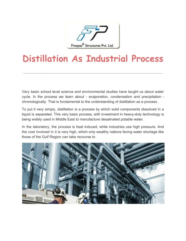
Introduction • Process Integration - definition • Motivation - energy savings, environment, innovation,... • Distillation is a very common separation process: • performs about 95% of fluid separations in the chemical industries. • Distillation is a very energy consuming process: • uses about 3% of the world total energy consumption. • accounts for around 25-40 % of energy usage in chemical and petroleum industry. • Process integration • saves energy and reduces the environmental impact of a process • reduce site utility costs (e.g. steam, cooling water) • may reduce capital costs
Introduction • Process Integration - definition • Motivation - energy savings, environment, innovation,… • Background to heat-integrated distillation columns • Multi-effect prefractionator arrangements have high energy savings - is therefore an interesting arrangement to study. • Operation of energy-integrated systems can be more difficult - want to operate so that the energy savings are achieved. • Not many publications on the control of the integrated prefractionator/sidestream columns [Cheng & Luyben, 1985, Ding & Luyben, 1990, Bildea & Dimian, 1999, Emtir et al., 2003]
Multi-Effect Distillation = where pressure is used to adjust the temperature levels in two (or more) columns so that the condensing duty of one column can be used to provide heat in the reboiler of another column.
forward-integration (F) backward-integration (B) Different Distillation Arrangements Direct split (DS) Indirect split (IS) B HP LP LP HP
Different Distillation Arrangements • 30 % less energy • prevents re-mixing effect of middle component • Further energy savings can be made with multi-effect integration. Thermally coupled columns: • Single column shell (divided wall column) • 30 % reduction in capital cost Prefractionator columns
Multi-Effect Prefractionator Forward integrated prefractionator (PF) Heat input Integrated reboiler/condenser
Multi-Effect Prefractionator Backward integrated prefractionator (PB) Integrated reboiler/condenser Heat input
Energy ConsumptionPercentage Savings of Different Energy Integrated Arrangements The integrated prefractionator arrangement is the best
Minimum Vapour Flowrate, Vmin • Vmin as a target - use to compare different designs • Minimum vapour flow at infinite number of stages • Can get within 10 % of Vmin target by using reasonable number of stages • Assumptions: ideal mixtures, constant relative volatility, constant molar flows, sharp splits • Can get within 10 % of Vmin-target using reasonable number of stages • Energy (V) vs. number of stages (N) • trade-off between number of stages and energy • actual V approaches Vmin for N approximately 2 x Nmin or larger, typically: 2Nmin + 20% Vmin 3Nmin + 2 % Vmin 4Nmin + 0.2 % Vmin
Vmin (PF/PB) PB/C PA/B VT/F PA/C = DC1/F Minimum Vapour Flowrate DiagramsA Visual Tool for Process Integration Vmin(C22) C21 C1 Vmin(C1) C21 Vmin(C21)
PB/C PA/B VT/F PA/C = DC1/F Drawing the Vmin-diagram Prefractionator column (C1): Reference: Halvorsen (2003) zA zA + zB Ref.: Halvorsen, Skogestad, 20003
PB/C PA/B VT/F PA/C = DC1/F Extending the Vmin-diagram Upper section main column (C21): PM3 PM2 Lower section main column (C22): PM4 PM1 zA zA + zB
Using the Vmin-diagramVapour Flowrate for Different Distillation Arrangements • Vmin for different arrangements. • Visualise how columns are (un)balanced. • 5 cases identified - different operating options available. Vmin (DSF/DSB) PB/C Vmin (Petlyuk + ISF/ISB) PA/B VT/F Vmin (PF/PB) PA/C Vmin(C1) = DC1/F
Benefits of the Vmin-diagram • Easy visualisation of minimum vapour flow. • Different distillation arrangements are presented in same diagram. • Tool for further design - balanced/unbalanced columns gives different design options. • Starting point for further rigorous simulations - Vmin target, optimum recovery = (D/F)
Control Problems with Heat-Integrated Distillation Columns • Integrated columns have added complexity. • Integrated columns may be difficult to controlas : • dynamic upsets can propagate back & forth between columns. • the system is non-linear, multivariable and interacting. • Energy savings may not be achieved (or may be worse) if the columns are not operated correctly. • The heat and mass integration of distillation columns causes additional control problemscompared to single columns. It is therefore essential to develop good control systems to ensure satisfactory operation
Implementing Optimal Operation of Multi-effect Prefractionators Objective: to implement a simple “optimal” control scheme for integrated distillation systems. Want to find the controlled variables that will directly ensure optimal economic operation. “Optimal” - means near-optimal operation. It is economically acceptable to be a certain distance from optimum (but not too far…).
Steady State Optimisation Objective : Selection of controlled variables Method: Self-optimizing control (Skogestad, 2000) The method of self-optimizing control involves a search for the variables that, when kept constant, indirectly lead to near-optimal operation with acceptableloss. Loss imposed by keeping constant setpoint for the controlled variable
Steady State Optimisation The method of self-optimizing control consists of six steps: 1) Finding the DOF for optimisation. 2) Formulation of a of cost function, J, to be maximised for optimal operations & constraints. 3) Identification of the most important disturbances. 4) Solving the nominal optimisation problem. 5) Identification of candidate controlled variables. 6) Evaluation of loss (at constant setpoints): L = J - Jopt Ref.: Sigurd Skogestad, "Plantwide control: the search for the self- optimizing control structure”, Journal of Process Control, 10, 2000.
Steady State Optimisation DOF analysisfor multi-effect columns : DOF= 11 - 4 = 7 Objective function: Operationalconstraints: • the LP column pressure must be 1 bar • the HP column pressure must be 15 bar • the purity of the products must be 99 mol% • there is a maximum area in the integrated reboiler/condenser • the duty of the HP condenser must equal the duty of the LP reboiler (equality constraint) • non-negative flows Process constraints - the mass, energy and component balances J = pDD + pSS + pBB - pFF - pVV
Steady State Optimisation DOF Accounts: 11 DOF total - 4 active constraints - 4 levels with no steady state effect - 1 fixed feedrate - 1 controlling distillate composition = 1 DOF left for self-optimising control Results from optimisation: • Active constraints: • Pressure in LP column • Product purity of sidestream • Product purity of bottom stream • Area in integrated exchanger • Non-active constraints: • pressure in HP column • product purity in distillate Implement active constraint control + control distillate composition One DOF left for control - find a self-optimising control variable
Steady State Optimisation • Calculate loss L = (J - Jopt) for the selected disturbances (zF, F). • Identify the best variable(s) for control, where the loss is small. Result: Control DHP/F
Implementing Optimal Operation of Multi-Effect Prefractionators
Dynamic Simulations • System is controllable. • System is sensitive to disturbances. • The control of bottom composition (main column) is poor. • Use of feed tank to reduce the feed disturbances (zF, F) • Other control configurations possible. 5 % increase in feedrate F 0.5 increase in middle component feed (zF)
An Industrial Separation Example 3 cases for integration: • Column I and II • Column II and III • Column III and IV Minimum vapour flowrates: • Case 3 has highest savings of 55 % • PF/PB is the best • ISF/ISB is 2. best
Possible Integration for Case III Indirect Split (IS) PF ISF (existing arrangement) Energy savingsfrom rigorous simulations:
Lessons from the Industrial Example • PF requires more stages to achieve potential energy savings. • Revamp should therefore be accompanied by an increase in number of stages. • If sufficient number of stages are allowed the rigorous simulations show that the PF arrangement has high energy savings (57 %). • The challenge is to implement the arrangement and achieve the savings in practice !
Main Contributions • Comparison of multi-effect prefractionator with other multi-effect arrangements and non-integrated arrangements. • Graphical visualisation of minimum energy for the multi-effect arrangements in a Vmin-diagram. • Systematic method applied in the selection of controlled variables for the forward integrated prefractionator arrangement. Control variables are identified that will give low energy losses during operation. • Analysis of the integrated prefractionator arrangement in an industrial setting .
Concluding Remarks • Focus of work is on the energy savings of multi-effect systems, especially the integrated prefractionator arrangement. • Screening of multi-effect arrangements are based on minimum vapour flow at infinite number of stages (PF/PB can achieve up to 70 % savings). • Minimum vapour flow (Vmin) is a good target, as by adding stages the actual value of vapour flow (V) is usually close to the minimum. • The energy requirements for multi-effect arrangements are visualised in Vmin-diagrams. • Selection of controlled variables using the systematic method of self-optimising control. • Controlling the right variables can give low energy losses during operation. • Industrial case study - high energy savings if sufficient number of stages are allowed.
References Bildea, C.S., Dimian, A.C., 'Interaction between design and control of a heat-integrated distillation system with prefractionator', Tans IChemE, 1999, Vol. 77, Part A, pp. 597-608 Cheng, H. C., Luyben, W., 'Heat-integrated distillation columns for ternary separations', Ind. Eng. Chem. Process Des. Dev., 1985, 24, 707-713 Ding, S.S., Luyben, W., ‘Control of a heat-integrated complex distillation configuration’, Ind. Eng. Chem. Res.¸1990, 29, 1240-1249 Emtir, M., Mizsey, P., Fonyó, Z., ' Economic and controllability investigation and comparison if energy integrated distillation schemes', Chem. Biochem. Eng. Q., 2003,17(1), 31-42 Halvorsen, I.J, Skogestad, S., ‘Minimum energy consumption in multicomponent distillation. 1. Vmin diagram for a two product column’, Ind. Eng. Chem. Res., 2003, 42, 596-604 Hewitt, G., Quarini, J., Morell, M., ‘More efficient distillation’, The Chemical Engineer, 21 Oct. 1999 Skogestad, S., 2000, Plantwide control: the search for the self-optimizing control structure, J. Proc. Control, Vol.10, 487-507.
Study Trip…. … sampling at the Glenfiddich Distillery, Scotland and Jameson Distillery, Ireland.
Practical Considerations for the Multi-Effect Prefractionator When considering a multi-effect distillation system for a practical application it is important to look at: • Operating costs (energy) • Capital costs • Total annual costs (operating + capital) • Control • Operability • Flexibility • Integration with overall process Usually these factors are not independent and a trade-off must be made to achieve an “optimal” design.