Download
1 / 16
160 likes | 236 Views
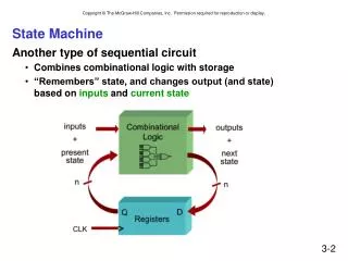
State Machine Implementation. 10/2/2008. ECE 561 - Lecture 5. 1. Lecture Overview. Another Example – a counting machine Another Example – Tail light controller. 10/2/2008. ECE 561 - Lecture 5. 2. Counting Machine.

E N D
State Machine Implementation 10/2/2008 ECE 561 -ECE 561 - Lecture 5 ECE 561 - Lecture 5 1
Lecture Overview • Another Example – a counting machine • Another Example – Tail light controller 10/2/2008 ECE 561 -ECE 561 - Lecture 5 ECE 561 - Lecture 5 2
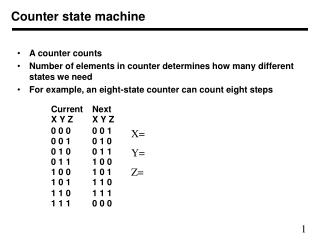
Counting Machine • “Design a clocked synchronous state machine with two inputs, X and Y, and one output Z. The output should be 1 inputs on X and Y since reset is a multiple of 4, and 0 otherwise. • There are 4 states 10/2/2008 ECE 561 -ECE 561 - Lecture 5 ECE 561 - Lecture 5 3
Construct a state table • From word description construct a state table for the problem. 10/2/2008 ECE 561 -ECE 561 - Lecture 5 ECE 561 - Lecture 5 4
Do a state assignment • Having state table pick a state assignment • From here we can generate the excitation equations ECE 561 -ECE 561 - Lecture 5
Excitation Equations • D1 = Q2 X’ Y + Q1’ X Y + Q1 X’ Y’ + Q2 X Y’ • Z = Q1’ Q2’ • D2 = Q1’ X’ Y + Q1’ X Y’ + Q2 X’ Y’ + Q2 X Y ECE 561 -ECE 561 - Lecture 5
Another Example • Design a clocked synchronous state machine with one input X and two outputs, UNLK and HINT. The UNLK output should be 1 if and only if X is 0 and the sequence of inputs received on X the preceding seven clock ticks was 0110111. The HINT output should be 1 if and only if the current value of X is the correct one to move the machine close to being in the “unlocked” state (with UNLK = 1). ECE 561 -ECE 561 - Lecture 5
Create State Table • Create a state table from the word description ECE 561 -ECE 561 - Lecture 5
Choose a state assignment • To get transition/excitation table ECE 561 -ECE 561 - Lecture 5
Can use Karnaugh Map to get excitation equations • D1 = Q1 Q2’ X + Q1’ Q2 Q3 X’ . + Q1 Q2 Q3’ • D2 = Q2’ Q3 X + Q2 Q3’ X • D3 = Q1 Q2’ Q3’ + Q1 Q3 X’ + Q2’ X’ . . + Q3’ Q1’ X’ + Q2 Q3’ X • UNLK = Q1 Q2 Q3 X’ • HINT = Q1’ Q2’ Q3’ X’ + Q1 Q2’ X . + Q2’ Q3 X + Q2 Q3 X’ + Q2 Q3’ X ECE 561 -ECE 561 - Lecture 5
For both examples • Having the excitation and output equation can do the implementation in discrete logic or perform a schematic capture for FPGA tools such as XILINX or Altera. ECE 561 -ECE 561 - Lecture 5
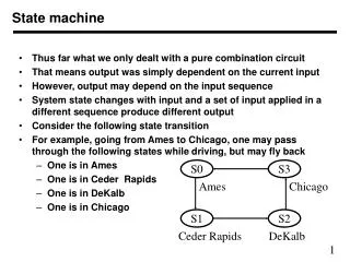
Another example • This is a example of a “real” deisgn • The T-Bird Tail Light Problem ECE 561 -ECE 561 - Lecture 5
The Transistion Table • Can again get the transition table ECE 561 -ECE 561 - Lecture 5
The State Diagram • Can also draw a state diagram ECE 561 -ECE 561 - Lecture 5
Final steps • Choose F/F type • Choose a state assignment • Develop the transition/excitation table for that state assignment • Generate the equations ECE 561 -ECE 561 - Lecture 5
Assignment 3 • Carry through the remaining steps to get implementation and output equations and the circuit diagram for an implementation for the following state table. ECE 561 -ECE 561 - Lecture 5