Download

1 / 29
340 likes | 552 Views
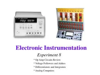
Part I: Amplifier Fundamentals. Agenda. Ideal Amplifiers Configurations and Operation of Amplifiers Common Amplifier Source Errors Understanding Amplifier Specification. Why So MANY AMPS???. Lots of Specifications Some are Important for Different Applications

E N D
Agenda • Ideal Amplifiers • Configurations and Operation of Amplifiers • Common Amplifier Source Errors • Understanding Amplifier Specification
Why So MANY AMPS??? • Lots of Specifications • Some are Important for Different Applications • Each Amplifier is Designed to Improve or Optimize One or a Combination of Specifications • No Ideal Op Amp; YET? • Specialty Amps for a Variety of Applications and Functions • Current Amplifier Trends • Power Consumption - Driven by portable applications • Rail-to-Rail – Higher Dynamic range on lower supply voltage • Smaller Packaging – Circuit density in portable applications • Price – Higher Performance at lower Price
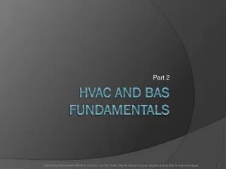
+ G X Y - What is an “Ideal” Op Amp? VIN • Amplifies a small signal (X) to a larger signal (Y) by Gain of G • Ideal Op Amp Characteristics • Voltage at + Input = Voltage at - Input • Infinite Input Impendence • Zero Output Impendence • Infinite Open Loop Gain • In closed loop Negative Input=Positive Input • Infinite Bandwidth VOUT
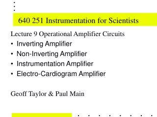
+ - Standard Configurations VIN Non-Inverting R2 VOUT R1 Inverting R2 VIN R1 + - VOUT
Operation of an “Ideal” Inverting Amplifier Virtual Ground Because +VIN = -VIN I2 R2 I1 Vin Vout + - R1
Operation of an “Ideal” Non-Inverting Amplifier Vin Vout + - R2 V1 I1 R1
Gain-bandwidth product • GBW product = Gain x BandWidth AOL 100000 GBP=1,000,000 10000 GBP=1,000,000 X 1000 ACL X 100 10 1
Nothing is ideal, friends.. • Real Characteristics • Finite open loop gain • Offset voltage • Input bias & offset currents • Finite bandwidth • And, these amplifiers are not free… IDEAL -+ REAL
-+ Input Error Sources • VOS – The difference in voltage between the inputs [~mV] Ideal Input Impedance (ZIN) Output Impedance (ZOUT) - A + Input Offset Current (Ios) Input Bias Current (Ib) Offset Voltage (Vos) • IB – The Current into the Inputs [~pA to mA] • IOS – The difference between the + IB and – IB [~IB /10] • ZIN – Input Impedance [MW to GW] • ZOUT – Output Impedance [<1W]
Bias Current Drift and Offset Voltage Drift • Offset Voltage is affected by the temperature • Drift is Usually in Units of mV/ ºC • Often a minimum and maximum VOS is Specified over the Temperature Range of the amp • Bias Current is also affected by temperature • Drift is Usually in Units of nA/ ºC • Often a minimum and maximum I BIAS is Specified over the Temperature Range of the amp • FET amplifiers have the lowest input Bias current
+ Very Low Bias CurrentFast FETs ™Amplifier Family Applications R2 • Photodiode Isc is linear over 6-9 decades and is usually in the range of pA-mA • Sensitivity is determined by amount of Isc multiplied by R2 • Minimizing Ib will ensure the highest possible sensitivity of the system • Additionally, maximizing the bandwidth minimizes the effects of Ib • Low DC Errors • Low Ibias, Vos and Drift • Low Noise • High-Speed Isc Ib AD8065 Precision Photo Diode Pre-Amp
Noise Gain • Noise Gain - gain of error signals (VER) between the inputs • Non-Inverting noise gain = Voltage Gain [R2/R1] • Inverting Noise gain = absolute value of the Voltage Gain +1 I R2 I Vout + - VER R1
All Input Error Sources End up at the Output • Input Referred Errors are multiplied by the Noise Gain • Initial VOS and VOS Drift Shift VOUT from the expected DC level • VOS drift multiplied by the change in temperature in ºC • Example: 2mV initial offset + 10mV/C with 100C shift and a gain of 5 creates 15mV offset at the output. • IB and IB drift with resistance (R1IIR2) at the summing node effectively create an additional VOS • Example: 10mA and R1 = R2 = 2k creates 10mV offset IB R2 IB=10mA Vout + - R1
Voltage or Current Noise Density CORNER FREQUENCY FREQUENCY Input Voltage and Current Noise • 2 Sources of Voltage and Current Noise • Low frequency Noise • Magnitude Increases as frequency decreases (1/f) • Wideband noise is flat over frequency • Usually Specified in Noise Density [nV/Hz and pA/Hz] • Multiply by the square root of the frequency range to determine the RMS noise • The intersection is referred to as the corner frequency
4V + 4mV - -4V 4V -4mV -4V Common Mode Rejection Ratio (CMRR) & Power Supply Rejection Ratio (PSRR) • CMRR is a ratio (output to input) of amplifier’s ability to reject an equal signal on both of the inputs • Similarly, PSRR is a ratio (output to power supply variation) of amplifier’s ability to reject power supply noise
Rail to Rail Amplifiers • Rail-to-rail amplifiers maximize signal swing, either on the input, the output or both. • True Rail-Rail op amps can swing to within a few mV of their power supply rails. • Non rail-to-rail op amps usually require between 1-3 volts of headroom to the supply rail • Analog Devices Rail to Rail Amplifiers • Rail to Rail Output • Fast FETsTM • AD8091/2 Very Low Cost, High-Performance • Rail To Rail Input • AD8031/2 Low Power High-Speed
Rail to Rail vs. Non Rail to Rail Amplifiers VIN +VS Out -VS In VOUT In +VS R-R Out -VS
Output Swing • Operating Region Decreases with Increased Frequency • Output Power [dBm] = 10log[V2rms/(RL)] x1mW Vout Saturation Increasing Frequency Vout Operating Region Iout Short Circuit Iout
Low-Power, Application Considerations • Minimize supply voltage circuitry or battery requirements • Reduce cooling requirements • Lower Heat Dissipation Saves Cost and Space • Smaller heat sinks • Essential in higher density PCB • Increases system stability and reliability • Example: • System with 5 AD8058 • (+/-5V)*(6.5mA/amp max)* (10 amps) = 650mW • Using AD8039 • (+/-5V)*(1.7mA/amp max)* (10 amps) = 170mW • ½ W Power savings
50 Open Loop Gain vs Freq.. 40 Gain 180 30 225 Degrees 270 20 315 AOL (dB) 10 Phase margin Phase 0 360 405 -10 -20 450 0.01 0.1 1 10 100 1000 Frequency (MHz) Relation Between Open Loop Gain and Phase • Oscillation will occur when Phase Delay 360° and a Gain >0dB • Phase Margin is the phase remaining before oscillation where the gain curve crosses 0dB • Margin of Less than 30 degrees is too little for safe operation
Why Phase Margin is Important • Excessive Peaking in the closed Loop Frequency Response will reduce the phase margin. • In the Time Domain, Low Phase margin causes Ringing • Reducing phase margin further will create sustained ringing or oscillation
Slew Rate and Large Signal Bandwidth • Slew Rate Determines the Limit for Large Signal Bandwidth Maximum Change in Voltage Change in Time High Slew Rate AD8014 + X Y - Slew Limited
10 0 -10 -20 -30 -40 [dB] -50 -60 -70 -80 -90 -100 5 10 -110 15 25 30 20 -120 Frequency [MHz] Distortion • Changes in the output wave form relative to the input wave form • For pure sign wave in, the output will have some energy at multiples of the input frequency - harmonics Fundamental 3rd 2nd
Rf Rg AD8007 + Ultra Low-Distortion and Noise Applications • Ideal for Buffering ADC Driver • Other Applications • IF/Baseband Amplifiers • Precision Instruments • Baseband and Video Communications • Pin Diode Receivers • Precision Buffer Passive Filter
Various Distortion Specifications • THD – used for Audio and other systems • Total Harmonic Distortion - sum of all distortions at all harmonics • Usually 2nd and 3rd harmonics contribute the most • SFDR - used for communications and other systems • Spurious-Free Dynamic Range in dB • Range between the input signal and largest harmonic
NEW High Value, Low Price Products • Fast FETsTM • AD8034 and AD8065 • The Highest Bandwidth per Dollar among all FET input Amps $1.19 @ 1k (AD8034) • Precision FET (PRA) • Low-Cost High-Performance • AD8091/2 • $0.69 @ 1k (AD8091) • Auto Zero (PRA) • Fast Speed-Low Power • AD8038 and AD8039 • Highest Speed per mA at only $0.85 @ 1k (AD8038) • CMOS (PRA) • Low Distortion, Low Power • AD8007/8 • Best Distortion at specified Is at only $1.19 @ 1k (AD8007)
Sewing Needle mSOIC SC70 SOIC SOT23 Packaging Considerations • All of the Amplifiers are available in small packaging • Maximizes the density of the board • Refer to the datasheet for particular amplifier package
To Be Continued… Part II: Various Amplifier Configurations