Download

1 / 31
3.01k likes | 6.56k Views
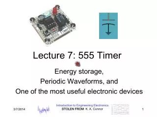
IC 555 TIMER. M.S.P.V.L. Polytechnic College, Pavoorchatram. What is the 555 timer?. The 555 timer is one of the most remarkable integrated circuits ever developed. It comes in a single or dual package and even low power cmos versions exist - ICM7555.

E N D
IC 555 TIMER M.S.P.V.L. Polytechnic College, Pavoorchatram
What is the 555 timer? • The 555 timer is one of the most remarkable integrated circuits ever developed. It comes in a single or dual package and even low power cmos versions exist - ICM7555. • Common part numbers are LM555, NE555, LM556, NE556. The 555 timer consists of two voltage comparators, a bi-stable flip flop, a discharge transistor, and a resistor divider network.
Inside the 555 Timer • The voltage divider (blue) has three equal 5K resistors. It divides the input voltage (Vcc) into three equal parts. • The two comparators (red) are op-amps that compare the voltages at their inputs and saturate depending upon which is greater. • The Threshold Comparator saturates when the voltage at the Threshold pin (pin 6) is greater than (2/3)Vcc. • The Trigger Comparator saturates when the voltage at the Trigger pin (pin 2) is less than (1/3)Vcc
The flip-flop (green) is a bi-stable device. It generates two values, a “high” value equal to Vcc and a “low” value equal to 0V. • When the Threshold comparator saturates, the flip flop is Reset (R) and it outputs a low signal at pin 3. • When the Trigger comparator saturates, the flip flop is Set (S) and it outputs a high signal at pin 3. • The transistor (purple) is being used as a switch, it connects pin 7 (discharge) to ground when it is closed. • When Q is low, Qbar is high. This closes the transistor switch and attaches pin 7 to ground. • When Q is high, Qbar is low. This open the switch and pin 7 is no longer grounded
What are the 555 timer applications? • Applications include • precision timing, • pulse generation, • sequential timing, • time delay generation and pulse width modulation (PWM).
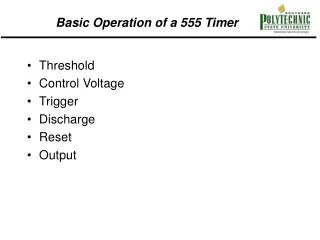
Pin Functions - 8 pin package • Ground (Pin 1) • Not surprising this pin is connected directly to ground. • Trigger (Pin 2) • This pin is the input to the lower comparator and is used to set the latch, which in turn causes the output to go high. • Output (Pin 3) • Output high is about 1.7V less than supply. Output high is capable of Isource up to 200mA while output low is capable of Isink up to 200mA. • Reset (Pin 4) • This is used to reset the latch and return the output to a low state. The reset is an overriding function. When not used connect to V+.
Control (Pin 5) • Allows access to the 2/3V+ voltage divider point when the 555 timer is used in voltage control mode. When not used connect to ground through a 0.01 uF capacitor. • Threshold (Pin 6) • This is an input to the upper comparator. • Discharge (Pin 7) • This is the open collector to Q14 in figure 4 below. • V+ (Pin 8) • This connects to Vcc and the Philips databook states the ICM7555 cmos version operates 3V - 16V DC while the NE555 version is 3V - 16V DC. Note comments about effective supply filtering and bypassing this pin below under "General considerations with using a 555 timer"
Types of 555-Timer Circuits • Astable Multivibratorputs out a continuous sequence of pulses • Monostable Multivibrator (or one-shot) puts out one pulse each time the switch is connected
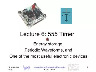
Behavior of the Monostable Multivibrator • The monostable multivibrator is constructed by adding an external capacitor and resistor to a 555 timer. • The circuit generates a single pulse of desired duration when it receives a trigger signal, hence it is also called a one-shot. • The time constant of the resistor-capacitor combination determines the length of the pulse.
Uses of the Monostable Multivibrator • Used to generate a clean pulse of the correct height and duration for a digital system • Used to turn circuits or external components on or off for a specific length of time. • Used to generate delays. • Can be cascaded to create a variety of sequential timing pulses. These pulses can allow you to time and sequence a number of related operations.
Behavior of the Astable Multivibrator • The astable multivibrator is simply an oscillator. The astable multivibrator generates a continuous stream of rectangular off-on pulses that switch between two voltage levels. • The frequency of the pulses and their duty cycle are dependent upon the RC network values. • The capacitor C charges through the series resistors R1 and R2 with a time constant (R1 + R2)C. • The capacitor discharges through R2 with a time constant of R2C
Uses of the Astable Multivibrator • Flashing LED’s • Pulse Width Modulation • Pulse Position Modulation • Periodic Timers
Flashing LED’s • 40 LED bicycle light with 20 LEDs flashing alternately at 4.7Hz
Understanding the Astable Mode Circuit • 555-Timers, like op-amps can be configured in different ways to create different circuits. We will now look into how this one creates a train of equal pulses, as shown at the output.
First we must examine how capacitors charge • Capacitor C1 is charged up by current flowing through R1 • As the capacitor charges up, its voltage increases and the current charging it decreases, resulting in the charging rate shown
Capacitor Charging Equations • Capacitor Current • Capacitor Voltage • Where the time constant
Understanding the equations • Note that the voltage rises to a little above 6V in 1ms.
Capacitor Charging and Discharging • There is a good description of capacitor charging and its use in 555 timer circuits at http://www.uoguelph.ca/~antoon/gadgets/555/555.html
555 Timer • At the beginning of the cycle, C1 is charged through resistors R1 and R2. The charging time constant is • The voltage reaches (2/3)Vcc in a time
555 Timer • When the voltage on the capacitor reaches (2/3)Vcc, a switch (the transistor) is closed (grounded) at pin 7. • The capacitor is discharged to (1/3)Vcc through R2 to ground, at which time the switch is opened and the cycle starts over.
555 Timer • The frequency is then given by
555 Animation Output is high for 0.693(Ra+Rb)C Output voltage high turns off upper LED and turns on lower LED Capacitor is charging through Ra and Rb • http://www.williamson-labs.com/pu-aa-555-timer_slow.htm
555 Animation Output is low for 0.693(Rb)C Output is low so the upper LED is on and the lower LED is off Capacitor is discharging through Rb
PWM: Pulse Width Modulation • Signal is compared to a sawtooth wave producing a pulse width proportional to amplitude
What Can Be Done With PWM? Low Duty Cycle • Question: What happens if voltages like the ones above are connected to a light bulb? Answer: The longer the duty cycle, the longer the light bulb is on and the brighter the light. Medium Duty Cycle High Duty Cycle
What Can Be Done With PWM? • Average power can be controlled • Average flows can also be controlled by fully opening and closing a valve with some duty cycle
The End …..Thank you…..