Download

1 / 22
1.14k likes | 3.26k Views
WATER LEVEL CONTROLLER USING 555 TIMER. By, Department of TCE/ECE JNNCE , Shimoga. OBJECTIVE: Automatic Control of AC Motor Thus Preventing overflow from Over Head Tank. OVERVIEW :. AC MOTOR. M. OVER HEAD TANK. Upper. CIRCUIT BOARD. Lower. GND.

E N D
WATER LEVEL CONTROLLER USING 555 TIMER By, Department of TCE/ECEJNNCE , Shimoga
OBJECTIVE: • Automatic Control of AC Motor • Thus Preventing overflow from • Over Head Tank.
OVERVIEW : ACMOTOR M OVER HEAD TANK Upper CIRCUIT BOARD Lower GND
CIRCUIT BOARD BLOCK DIAGRAM: 555 TIMER IC Input From OHT DRIVER RELAY
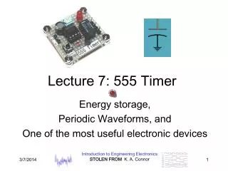
ABOUT THE 555 TIMER IC • Introduced in 1972 by Hans Camenzind • at Signetics Corporation. Low cost , stable , low power. • Manufactured 1 billion units / year . • 8 pin mini DIP-8 pack. • Includes 25 Transistors ,2 diodes and 15 resistors • in silicon chip. • Used in timer , pulse generation and Oscillator applications .
Pin Details: 1 – GND : Ground, low level (0 V) 2 – TRIGGER : Detects 1/3Vcc, Output high. Pin 2 controls over Pin 6. 3 - OUTPUT :This output is driven to approximately 1.7V below +V cc or GND 4- RESET :A timing interval may be reset by driving this input to GND
5 – CONTROL : Control access to the internal voltage divider (by default, 2/3 VCC). 6 – THRESHOLD : The interval ends when the voltage at THRESHOLD is greater than at CONTROL. 7 - DISCHARGE : Open collector output; may discharge a capacitor between intervals. 8- VCC : Positive supply voltage.( 3 to 15V)
Specifications of NE555:1) Supply Voltage : 3 to 15 V 2) Supply Current : 3 to 15 mA 3) Output Current : 200mA (MaX) 4) Power Consumption : 225 mW @ 15V
Modes of Operation: • Astable : Free Running mode, used as oscillator , • provide time delay, adjust duty cycle. • 2) Monostable : "one-shot" pulse generator. • Applications include timers, • bounce free switches. • 3) Bistable: Basic flip-flop , Schmitt trigger.
555 ANALYSIS : + - + -
TRUTH TABLE : (SR FLIP FLOP) + - WATER CONTROLLER TRUTH TABLE : + -
*When Water Below LOWER LEVEL :Comparator 1 = high Comparator 2 = LowSR FLIP FLOP = SET (1) , Q bar ( OUTPUT ) = Low (DRIVES THE RELAY)*When Water Level Reaches UPPER LEVEL:Comparator 1= Low Comparator 2= HighSR FLIP FLOP = RESET (0) , Q bar (OUTPUT) =High ( RELAY OFF)
WORKING ANALYSIS: MOTOR SWITCHES “OFF” MOTOR SWITCHES “ON”
RELAY : An Electromagnetic Switch Relay Open : Common - Normally closed (NC) Relay Closed : Common – Normally open (NO)
An Astable Circuit has no stable state - hence the name "astable". The output continually switches state between high and low without any intervention from the user, called a 'square' wave. This type of circuit could be used to give a mechanism intermittent motion by switching a motor on and off at regular intervals. It can also be used to flash lamps and LEDs, and is useful as a 'clock' pulse for other digital ICs and circuits.
A Monostable Circuit produces one pulse of a set length in response to a trigger input such as a push button. The output of the circuit stays in the low state until there is a trigger input, hence the name "monostable" meaning "one stable state
A Bistable Mode or a Schmitt Trigger, has two stable states, high and low. Taking the Trigger input low makes the output of the circuit go into the high state. Taking the Reset input low makes the output of the circuit go into the low state. A push button would be placed at each end of the track so that when one is hit by the train, it will either trigger or reset the bistable.