Download
1 / 44
450 likes | 613 Views
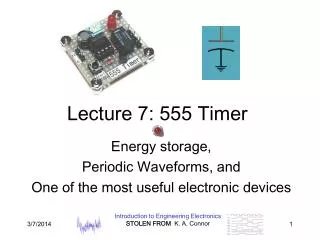
Chris Whiting & Keddy Malcolm. Music Synthesis Using the 555 Timer. Overview. 555 Timer Pin Layout 555 Timer Configuration 555 Timer – Other Applications Malcolm Results Whiting Results Conclusion Sources. 555 Timer Pin Layout. 555 Timer Pin Descriptions.

E N D
Chris Whiting & Keddy Malcolm Music Synthesis Using the 555 Timer
Overview • 555 Timer Pin Layout • 555 TimerConfiguration • 555 Timer – Other Applications • Malcolm Results • Whiting Results • Conclusion • Sources
555 Timer Pin Descriptions • Square wave output, how? • Capacitor Charge Time: T1 = 0.693(R1+R2)C1 • Capacitor Discharge Time: T2 = 0.693(R2)C1 • The output frequency is determined by the following equation: • Simple astableconfiguration
555 Timer Pin Descriptions • Duty Cycle of waveform – Pulse Width/Period • The Duty cycle is determined by the following equation: • Duty Cycle Relationship to output frequency • Large R2 wrt R1 • Control capacitor reduces noise
555 Timer - Other Applications • Two modes of operation: • MonostableMode – Output Single Pulse • AstableMode – Output Continuous Pulses • Bistable Mode – Output acts as Basic Flip-Flop • Linear Ramp • Pulse Width Modulator • Frequency Divider
555 Timer - Other Applications • Linear Ramp
555 Timer - Other Applications • Pulse Width Modulator
555 Timer - Other Applications • Frequency Divider
Malcolm-Design Overview Week 1 Switch Placement
Assembly Problems Week One: • Change resistors to get frequencies correct • Mistakes in wiring Week Two: • Problems with wiring • Balance between volume and waveform output • Component Precision
Waveform Results: 259 Hz • Rise time: 1.86 ms • Fall time: 1.76 ms • Duty Cycle: 51.38%
Waveform Results: 293 Hz • High Time: 1.64ms • Low Time : 1.66ms • Duty Cycle: 49.7%
Waveform Results: 329 Hz • High Time: 1.42ms • Low Time: 1.42ms • Duty Cycle: 50%
Waveform Results: 349 Hz • High Time: 1.41ms • Low Time: 1.41ms • Duty Cycle: 50%
Waveform Results: 391 Hz • High Time: 1.27ms • Low Time: 1.28ms • Duty Cycle: 49.80%
Waveform Results: 440 Hz • High Time 1.14ms • Low Time 1.12ms • Duty Cycle: 50.80%
Waveform Results: 493 Hz • High Time: 1.02ms • Low Time: 1.01ms • Duty Cycle: 50.44%
Waveform Results: 523 Hz • High Time: 968us • Low time: 948 us • Duty Cycle: 50.25%
Overall Results • Frequencies and duty cycle very accurate in first stage • Frequencies loose accuracy in the second stage • Excellent sine wave poor volume quality
Chris’ Final Circuit Diagram • Used potentiometers in the lab to more accurately obtain desired output frequencies
Chris’ 555 Timer Circuit • R2 value determines output frequency. • Duty Cycle unaffected because R2 >> R1 • Various switches with potentiometers are used to act as selectors for the output frequency by turning each switch on or off.
Chris’ Filter Circuit • 555 Timer Square Wave Output Sine Wave • A square wave is the sum of multiple sine waves at odd multiples of the square wave’s frequency (odd order harmonics)
Chris’ Filter Circuit • Extract the fundamental frequency of the square wave by filtering the higher order sine waves. • Low-pass filter with 600 Hz cutoff frequency and an inverting op-amp connected in series.
Chris’ Results – Square Wave • Theoretical & Experimental results for 555 timer circuit square wave output
Chris’ Results – Square Wave • Different resistances attributed to: • Potentiometers, inaccurate capacitors, 555 timer 18.52% Difference?!
Chris's Results – Sine Wave • Theoretical & Experimental results for 555 timer and filter combination sine wave output
Chris's Results – Sine Wave • Different resistances attributed to: • Potentiometers, inaccurate capacitors, 555 timer 20.08% Difference?!
Chris's Results – Sine Wave • Square wave to Sine Wave conversion • Duty Cycle = 50.0% • 0.2% error on average
Chris's Results – Sine Wave • Square wave to Sine Wave conversion • Duty Cycle = 50.0% • 0.2% error on average 524.091Hz 523.063Hz
Conclusion • 555 Timer Pin Layout • 555 Timer Configuration • 555 Timer – Other Applications • Malcolm Results • Whiting Results
Sources • http://blog.makezine.com/2008/01/29/how-to-guitar-hero-autowh/ • http://www.ecelab.com/circuit-astable-555.htm • http://www.cc.gatech.edu/classes/AY2011/cs3651_spring/docs/LM555.pdf • http://home.cogeco.ca/~rpaisley4/LM555.html