Download
1 / 7
70 likes | 93 Views
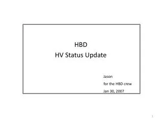
HBD HV status and plans. Itzhak Tserruya Special meeting, BNL January 29, 2007. Resistive Chain. Outside HBD. = 2.2M . Inside HBD. 28 HV segments in each GEM. R2=20M . Top GEM. = 10M . Middle GEM. Bottom GEM. Normal operation: HV= 3720V V GEM = 500V I = 150A

E N D
HBD HV status and plans Itzhak Tserruya Special meeting, BNL January 29, 2007
Resistive Chain Outside HBD =2.2M Inside HBD 28 HV segments in each GEM R2=20M Top GEM =10M Middle GEM Bottom GEM • Normal operation: HV= 3720V VGEM = 500V I = 150A • Dead short in one GEM: I increases by 1.56%
Status as of Jan. 26, 2007 • There are problems in 24 GEMs (out of 72): • 15 top • 5 middle • 4 bottom • Out of them: • 9 have a dead (or almost dead) short and the 10M has been replaced by a 20. • 9 draw high current with an almost ohmic behavior. The current ranges from 3 – 15A at about ~500V reflecting a GEM impedance of 16 – 140M. • 2 draw low current (410 and 777nA) at ~500V reflecting a very high GEM impedance (0.6 and 1.3 G). • 4 seem to have multi-strip problems and the 10M has been removed.
GEM test history • All GEMs were subject to the following tests: a) in open air & clean room (WI): • ohmic test before and after framing • 100 V test after soldering the 20M resistors b) Inside test box (WI): • 520 V in CF4 • 480-500V in Ar/CO2 during the single GEM gain mapping. c) Inside glove box (SUNY): • 550 V in pure N2 • ~350 V in Ar/CO2 during the final triple GEM gain mapping. c) After installation and prior of closing the HBD (SUNY): • 100V test and capacitance test
Diagnostics • There is no reason to believe that there was something wrong on the GEMs up to installation inside the HBD. • There is no reason to believe in some damaging chemistry between the CF4 and the CsI. We have accumulated experience (integral of several months of operation CF4 & CsI) and we never observed a problem. • The observations are consistent with dust inside the detector and/or some physical damage of the GEMs most likely during the transportation from SUNY to BNL. • Time may help sharpening this diagnostic or we may need to open the detector.
How to proceed The big question is: • Can we operate the HBD in the present conditions? To answer this question we should first answer the two following questions: - Is the status in CF4 the same as in N2? - Is the status stable with time? Proposal: • Change to CF4 • Raise the global voltage on all modules to app. 3500 V where we should see cosmic rays. If the detectors are stable over a few days: a) replace the 10M resistor in the 9 GEMs that draw current to restore the 500V across the GEM b) leave the 2 GEMs with very high impedance w/o change. The gain in these modules can be restored by slightly raising the global HV. c) leave the GEMs with multi-strip problems w/o resistor.