Download

1 / 19
190 likes | 355 Views
Status of the UCSB Gantry. Dean White University of California Santa Barbara October 2003. MODULE DATA - SENSORS. MODULE DATA HYBRIDS (1). HYBRID TO SENSOR ANGLE WAS NOT CONSISTENT AT FIRST. (MODULES 1 – 41, NEXT SLIDE )

E N D
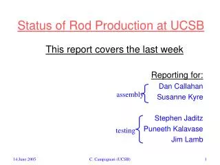
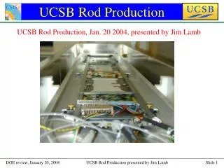
Status of the UCSB Gantry Dean White University of California Santa Barbara October 2003
MODULE DATA HYBRIDS (1) • HYBRID TO SENSOR ANGLEWAS NOT CONSISTENT AT FIRST. (MODULES 1 – 41,NEXT SLIDE) • AFTER INCREASING HYBRID CLAMPING PRESSURE, BY SHIMING THE HYBRID TOOLS, IT SEEMS TO BE MUCH MORE CONSISTENT. (MODULES 42-60,NEXT SLIDE)
MODULE DATA HYBRIDS (2) HYBRID CAME DOWN ON EDGE OF HV WIRE
Stereo Module • Have built 3 stereo modules (included in previous results).
Assembly Plates • 4 fully commissioned R-phi assembly plates • 1 prototype R-phi assembly plate (could be used if needed) • 1 fully commissioned Stereo assembly plate
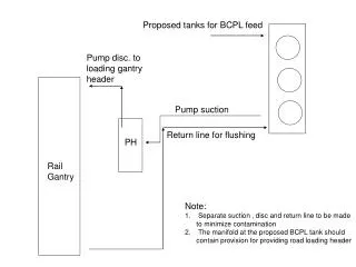
ASSEMBLY TOOLING (1) BREIF DISCUSSION OF THE DEVELOPMENT OF UCSB MODUDE ASSEMBLY TOOLING: • Z and U axis made orthogonal to to gantry base plate. • Aerotech U motor mounting bracket replaced
Assembly Tooling (2) 2. SUPPORT PADS FOR THE ASSEMBLY PLATES WERE MACHINED FLAT & PARALLEL BY THE GANTRY
ASSEMBLY TOOLING (3) 3. ASSEMBLY PLATE FEET MACHINED FLAT & PARALLELTO WITHIN 25um Sensor vacuum Hybrid vacuum Hybrid supply vacuum
ASSEMBLY TOOLING (4) 4. ASSEMBLY PLATE TEFLON PADS ARE MACHINED TO FINAL HEIGHTS (+/- 25um) REFERENCED OFF OF FEET ON BOTTOM Vacuum channels and o-ring grove machined into assembly plate for each sensor
ASSEMBLY TOOLING (5) 5. HYBRID AND SENSOR PICK-UP TOOLS. 6. HYBRID BRIDGE
Gantry/Data Base/OGP • Moving towards using OGP for final module surveys. • Andrea Allen (recent UCSB physics graduate/technician) has automated the OPG surveying of the modules, so that it is much faster than the gantry. • Andrea has written excel macros to compare the survey results with the nominals and output them to files for each position on each assembly plate. • The results are also output in a text file that can be incorporated into an xml file and uploaded to the DB. • This will allow module production on the gantry to start earlier each day. Will make it easier to do 12 modules/day if needed (probably will be). • The calibration factors used in the gantry are based on OGP surveys of the modules. Using the OPG surveys for the DB should slightly improve our results.
GANTRY 3RD POSITION PROBLEM • Did not see problem on R-phi assembly plates, except for occasional skipping of 3rd position thermistor glue points. • Problem was very evident on new stereo assembly plate. 8 of 10 dry runs on the 3rd position could not be completed. • Russell noticed that the problem looked like it was totally position dependent, so he wrote a program to count from 1-50 at points on a grid covering the gantry area we use. • Russell’s results showed a strip in the gantry Y axis between the 3rd and 4th rows of the calibration file where there were errors in the counting while sitting at those locations.
Gantry 3rd Position Problem Below are the results from this survey using our current calibration file that has calibration points on a 20mm grid. Miscounts occurred
Gantry 3rd Position Problem Below are the results from this survey using an old calibration file that has calibration points on a 40mm grid. Miscounts occurred between same strips
Gantry 3rd Position Problem • Solution : Russell added rows of dummy calibration points to move “bad area” off of assembly plate Dummy points
U600 Card • U600 controller cards & 4EN-PC expansion boards can not be ordered from Aerotech after the end of December 2003 (see Product Phase Out Notification). • Reason – There are chips on the boards that are no longer available. • Spares may or may not be available after December 2003. • UCSB has ordered 1 U600ultra w/32MB controller card. We want to see if it will help some areas where the gantry program is slow on our system. We currently have a U600base w/8MB controller card. • We will keep the U600base card as a US spare.
A3200 Controller Option • There is the option of replacing the U600 and expansion card with Aerotech’s current A3200 controller. • Basic process to convert to the A3200 – no guarantees! • Replace DR500 with 4 (one for each axis) A3200 controller/power supplies. • Each controller has 12 output ports and 14 input ports (expanded I/O version). • Control of gantry is done thru software and the 4 controller/power supplies. No cards put in computer. • Current I/O lines would have to be rewired from 4EN-PC expansion card to the four A3200 controller/power supplies. • Gantry program should run on A3200 controller without modification. • Cost ~ $12,500 USD
Other stuff… • Working on detailed instruction document for technicians (Andrea). • Russell has automated the insertion of sensor and hybrid numbers into gantry program from the DB. • Just made tool to check the overall length of the glue dispensing tool before module assembly. Creates an E-stop situation if it is too long. • Plan to do 45 module mini production run in one week (9 modules per day) in early November.