Download
1 / 48
2.72k likes | 6.55k Views
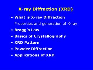
X-Ray Diffraction (XRD). What is XRD?. X-ray diffraction is a method of X-ray crystallography , in which a beam of X-rays strikes a sample (crystalline solid), land on a piece of film or other detector to produce scattered beams.

E N D
What is XRD? • X-ray diffraction is a method of X-ray crystallography, in which a beam of X-rays strikes a sample (crystalline solid), land on a piece of film or other detector to produce scattered beams. • These beams make a diffraction pattern of spots; the strengths and angles of these beams are recorded as the sample is gradually rotated. X-ray crystallography is a method of determining the arrangement of atoms within a crystal, in which a beam of X-rays strikes a crystal and scatters into many different directions.
What is XRD? • From the angles and intensities of the scattered beams, a crystallographer can produce a three-dimensional picture of the density of electrons within the crystal. • From this electron density, the mean positions of the atoms in the crystal can be determined, as well as their chemical bonds, their disorder and other information.
Diffraction Phenomenon • Diffraction occurs when a wave encounters a series of regularly spaced obstacles that • Capable of scattering the wave, • Have spacings that are comparable in magnitude to the wavelength. • Diffraction is a consequence of specific phase relationship between two or more waves that have been scattered by the obstacles.
Diffraction Phenomenon • Consider wave 1 and wave 2 which have the same wavelength, λ and are in phase at point O-O’. • Then, suppose that both waves are scattered in such a way that they traverse different paths. • If these two waves are still in phase , they will mutually reinforce (constructively interfere) one another. • The opposite is that when the path length difference after scattering is half wavelength. • The two waves are out of phase and will cancel one another – destructively interfere.
X-Ray Sources • X-rays used for diffraction are electromagnetic waves with short wavelengths in the range 0.05 – 0.25 nm. (wavelength on the order of the atomic spacings for solids) • To produce X-rays for diffraction purpose, a voltage of about 35 – 50 kV is necessary and applied between a cathode and an anode target metal, both are contained in a vacuum. • When the tungsten filament of the cathode is heated, electrons are released by thermionic emission and accelerated through the vacuum by the large voltage difference between anode and cathode. Thermion - An electrically charged particle (electron or ion) emitted by a substance at a high temperature.
X-Ray Sources Cross-section of filament x-ray tube
X-Ray Sources When the electrons strike the target metal, (e.g molybdenum) x-rays are given off (produces strong Kα and Kβ lines). The most common metal used is copper, which can be kept cool easily, due to its high thermal conductivity. X-rays are generally filtered to a single wavelength (made monochromatic) and collimated to a single direction before they are allowed to strike the crystal. The filtering not only simplifies the data analysis, but also removes radiation that degrades the crystal without contributing useful information. Most of the the kinetic energy (about 98%) is converted into heat, so the target metal must be cooled externally.
X-Ray Sources X-ray emission spectrum of Molybdenum which used as target metal in x-ray tube Origin of Kα and Kβ radiation
X-ray Sources • The spectrum (previous page) shows continuous x-ray radiation in the wavelength range about 0.02 – 0.14 nm. • There are two spikes of characteristic radiation : Kα and Kβlines. • The wavelength of the Kα and Kβlines are characteristic for an element. • For molybdenum, Kα = 0.07 nm (0.7 Å)
X-Ray Sources • The origin of the characteristic radiation (Kα and Kβ ) is explained below. • First, K electrons (electrons in the n = 1) are knocked out of the atom by highly energetic electrons bombarding the target, leaving excited atom. • Next, some electrons in higher shell (n = 2 or 3) drop down to the lower energy level to replace the lost K electrons, emitting energy of a characteristic wavelength. • The transition of electrons from the L (n=2) shell to the K (n=1) shell creates energy of the wavelength of the Kα line.
Bragg Diffraction • Bragg formulation of X-ray diffraction) was first proposed by William Lawrence Bragg and William Henry Bragg in 1913 in response to their discovery that crystalline solids produced surprising patterns of reflected X-rays. • In these crystalline solids, for certain specific wavelengths and incident angles, intense peaks of reflected radiation (known as Bragg peaks) were produced. Bragg diffraction
Bragg Diffraction • Bragg diffraction occurs when electromagnetic radiation or subatomic particle waves with wavelength comparable to atomic spacings, are incident upon a crystalline sample, scattered by the atoms in the system and undergo constructive interference in accordance to Bragg's law. • Since wavelengths of some x-rays are about equal to the distance between planes (d = interplanar distance) of atoms in crystalline solids, reinforced diffraction peaks of radiation varying intensities can be produced when a beam of x-rays strikes a crystalline solid.
The Bragg Condition • Consider monochromatic (single-wavelength) beam of x-rays to be incident on a crystal. • The horizontal lines represent a set of parallel planes with Miller indices (hkl)
The Bragg Condition • When an incident beam of monochromatic x-rays of wavelength λ strikes this set of planes at an angle such that the wave patterns of the beam leaving the various planes are not in phase, no reinforced beam will be produced. • If the reflected wave patterns of the beam leaving the various planes are in phase, then reinforcement of the beam or constructive interference occurs.
The Bragg Condition • Now consider incident x-rays 1 and 2 as indicated in the figure below. • For these rays to be in phase, the extra distance of travel of ray 2 is equal to MP + PN, which must be an integral number of wavelength λ. Thus, n λ = MP + PN n= 1,2,3… (order of diffraction)
The Bragg Condition • Since MP + PN equal to dhkl sin θ, where dhkl is the interplanar spacing of the crystal planes of indices (hkl), the condition for constructive interference must be: n λ = 2dhkl sin θ Bragg’s Law In most cases, the first order diffraction is used, so λ = 2dhkl sin θ
Diffraction Conditions for Cubic Unit Cells • The analysis of x-ray diffraction data for cubic unit cells can be simplified by combining Bragg equation with the interplanar spacing equation. λ = 2dhkl sin θ dhkl = a h2 + k2 + l 2 λ = 2a sin θ h2 + k2 + l 2
Diffraction Conditions for Cubic Unit Cells • The equation above (previous page) can be used along with x-ray diffraction data to determine if a cubic crystal structure is body-centered or face-centered cubic. • For simple cubic, reflection from all (hkl) planes are possible. • For BCC structure, diffraction occurs only on planes whose Miller indices when added (h+k+l) total to an even number. Eg: {110}, {200} • For FCC structure, diffraction occurs only on planes whose Miller indices are either all even or all odd. Eg: {111}, {200}
Interpreting XRD Data • XRD data can be used to determine crystal structure of metal with cubic crystal structures. • Let assume we have a metal with either a BCC or an FCC structure that we can identify the principal diffracting planes and their corresponding 2θ values. • Squaring both sides of equation , we obtain sin2 θ = λ2 (h2 + k2 + l 2) 4a2
Interpreting XRD Data • For BCC structure, the first two sets of principal diffracting planes are {110} and {200}. XRD data can be used to determine crystal structure of metal with cubic crystal structures. sin2 θA = hA2 + kA2 + lA2 sin2 θB hB2 + kB2 + lB2 sin2 θA = 12 + 12 + 0 2 = 0.5 sin2 θB 22 + 02 + 0 2 If the crystal structure of the unknown metal is BCC, the ratio of the sin2 θ that correspond to the first two principal diffracting planes will be 0.5
Interpreting XRD Data • For FCC structure, the first two sets of principal diffracting planes are {111} and {200}. sin2 θA = 12 + 12 + 1 2 = 0.75 sin2 θB 22 + 02 + 0 2 If the crystal structure of the unknown metal is FCC, the ratio of the sin2 θ that correspond to the first two principal diffracting planes will be 0.75
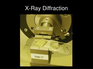
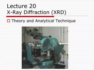
X-Ray Diffractometer • Definition – An instrument for studying crystalline materials by measurement of the way in which they diffract (scatter) x-rays of known wavelength. • Three (3) basic components of an x-ray diffractometer are: • X-ray source • Specimen/sample • X-ray detector They all lie on the circumference of a circle known as the focusing circle.
Geometry of X-Ray Diffractometer X-ray Source Detector
Geometry of X-Ray Diffractometer • The angle between the plane of the specimen and the x-ray source is . • The angle between the projection of the x-ray source and the detector is 2. • This geometry is often known as -2 scan. • Typically the 2 measurement range is between 0 –170 °. • The choice of scan depends on the crystal structure of the materials (if known) and for the unknown materials, a large range of scan often used because the positions of peaks are not known.
Geometry of X-Ray Diffractometer • Diffractometer circle is also known as goniometer circle. • Goniometer is the central component of an x-ray diffractometer and contains the specimen holder • It has arm to which the x-ray source and detector are mounted. • Usually goniometer is vertically mounted but those used for thin film studies are horizontally mounted. A goniometer is an instrument that either measures angle or allows an object to be rotated to a precise angular position. The term goniometry is derived from two Greek words, gonia, meaning angle and metron, meaning measure.
Specimen • Crystalline materials in forms of bulk, powder, sheet or thin films can be analyzed. • It is important that the specimen chosen is representative of the materials. • For powder specimen – a thin layer of crystalline powder is spread on to a planar substrate, which is often a nondiffracting material such as a glass microscope slide and exposed to x-ray beam.
Powder Specimen • Quantity of powder is about few mg. • The grain size of the powder should be less than 50 μm. • Ideally the specimen should contain numerous small, equiaxed randomly oriented grains. • If grain size smaller than 1 μm, broadening of the peaks in the diffraction pattern occurs. • If a mixture of two powders to be characterized, they must be thoroughly mixed.
The Detector • In the diffractometer, the intensity of the diffracted beam is measured directly by an electronic x-ray detector. • They are many types of detectors (sometimes called counters), but they all convert the incoming x-rays into surges or pulsed of electric current which are fed into various electronic components for processing. • The electronics counts the number of current pulses per unit of time, and this number is directly proportional to the intensity of the x-ray beam entering the detector.
The Detector • There are three main types of detector used in x-ray diffractometers. • Proportional • Scintillation • Semiconductor • For instrument dedicated for powder works, a proportional detector is probably used. • Scintillation, although still available is not widely used in new types of diffractometer. • Semiconductor detector offers many advantages. E.g very efficient.
Proportional Detector • Consisting of a cylindrical metal shell (the cathode) about 10 cm long and 2 cm in diameter filled with gas and containing • There is a fine metal wire (the anode) running along the shell axis and it is electrically isolated from the shell. • One end of the cylinder is covered by a window of high transparency to x-rays.
Proportional Detector • When an x-ray photon enters the tube through a thin window it is absorbed by an atom of the gas and causes a photo electron to be ejected. • The photoelectron loses its energy by ionizing other gas atoms. • The released electrons are attracted to the positively charged tungsten wire giving rise to a charge pulse. • The collected charge (the size of the pulse) is proportional to the energy of the incident photon, and hence the term “proportional detector”.
Scintillation Detector • In scintillation detector, the incident x-rays cause a crystal (sodium iodide – NaI) doped with 1% thallium to fluorescence. • For NaI doped with Tl+ the fluorescence is in the violet region of the electromagnetic spectrum. • A flash of light (scintillation) is produced in the crystal for every x-ray photon absorbed. • The amount of light emitted is proportional to the x-ray intensity and can be measured by the photo multiplier. The size of the pulse is proportional to the energy of the x-ray photon absorbed.
Semiconductor Detector • The detector is a single crystal consisting of a sandwich of intrinsic silicon between a p-type layer and n-type layer forming p-i-n diode. • When x-rays interact with the silicon crystal they excite electrons from the valence band into the conduction band, creating an electron-hole pair. • When a reverse bias potential is applied to the crystal, the electrons and holes are separated and a charge pulse of electrons can be measured.
Semiconductor Detector • The number of electrons and holes created is directly proportional to the energy of the incoming x-ray • The creation of electron-hole pairs in silicon is at 77K so the detector has to be cooled using liquid nitrogen. • Semiconductor detector is extremely efficient almost 100% almost all photons striking the detector are converted into pulses to be measured.
X-Ray Diffraction Pattern • This is a typical x-ray diffraction pattern. • The pattern consisits of aseries of peaks with various intensities. • The spectrum shows peak intensity vs. measured diffraction angle 2θ. • Each peak or reflection in the diffraction pattern corresponds to the x-rays diffracted from a specific set of planes in the specimen.
X-Ray Diffraction Pattern • The intensity is proportional to the number of x-ray photons of a particular energy that have been counted by the detector for each angle 2θ. • It is the relative intensities of the peaks that we are interested and the relative differences in their integrated intensity (area under the peak). • The pattern should be used to locate the peak positions. • The positions of the peaks in an x-ray diffraction pattern depend on the crystal structure (shape and size of the unit cell) of the materials.
PEAK HEIGHT FWHM Integrated peak Intensity Angular peak position Diffraction Pattern Information Peak position Structure Intensity (Height) Quantity FWHM Crystallite size
X-Ray Diffraction Pattern • Number of peaks depend on the symmetry of the crystal structure. • Decrease in symmetry will increase the number of peaks. • Example: Cubic crystal structure has fewer peaks while hexagonal structure has more peaks in its diffraction patterns. • Diffraction patterns from cubic materials can be easily distinguished at a glance from these non-cubic structured materials.
X-Ray Diffraction Pattern • For simple cubic and BCC structures, the peaks are equally spaced. • In FCC structure, the peaks appear alternatively as a pair and a single peak. • In diamond cubic structure, the peaks are alternatively more widely spaced. • The intensities of the reflections in single phase materials provide us with information about the atom positions in the crystal. • The width of an individual peak, often defined as the full width at the half maximum height can be used to determine the crystallite size and the presence of lattice distortions.
Body Centred Cubic Face Centred Cubic X-Ray Diffraction Pattern
X-Ray Diffraction Pattern • Diffraction pattern is a “fingerprint” of specific solid state form. • Position of just one isolated peak does not characterize material or his solid state form. • Intensity of diffraction peaks are related to the quantity of particular phase present in specimen. • Powder pattern is 1D picture of 3D structure. • Powder pattern characterizes material by it’s structure, so it is very good for phase identification. • Intensities in an XRD pattern are in relation with quantity of analyzed material, so it can be used to determine quantitative ratio of phases in mixture.
X-Ray Diffraction Pattern Counts Crystalline Form A 10000 Multi-phase sample 5000 Crystalline Form B 15 20 25 30 Amorphous Position [°2Theta] Counts 4000 Resulting XRD pattern 2000 10 15 20 25 30 Position [°2Theta]
X-Ray Diffraction Pattern • Most modern XRD instruments perform peak search using computer, in addition the computer also compute the 2θ angles, and the integrated intensities for each peak. • Most commercial software allows the user to compare standard pattern (from database) with experimentally observed patterns-rapid matching and identification. • Certain software packages also allow to: • Determine lattice strain • Calculate crystallite size • Refine calculation of lattice parameters. • Calculate diffraction patterns etc.
Design and Use of the Indexes for Manual Searching of the PDF (powder diffraction file) • Three search methods are used in the indexes – i.e. • The alphabetical index; • The Hanawalt index • The Fink index.
Applications Enable us to quickly analyze unknown materials and perform materials characterization in such fields as metallurgy, mineralogy, forensic science, archeology, condensed matter physics, and the biological and pharmaceutical sciences. Identification is performed by comparison of the diffraction pattern to a known standard or to a database such as the International Center for Diffraction Data's Powder Diffraction File or the Cambridge Structural Database (CSD).