Download
1 / 6
60 likes | 64 Views
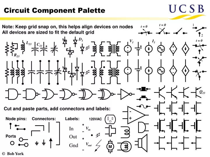
1. 2. -. +. M. Circuit Component Palette. Note: Keep grid snap on, this helps align devices on nodes All devices are sized to fit the default grid. t = 0. t = 0. D 1. V 1. I 1. t = 0. L 23. C 23. R 23. Q 23. Cut and paste parts, add connectors and labels:. Node pins:.

E N D
1 2 - + M Circuit Component Palette Note: Keep grid snap on, this helps align devices on nodes All devices are sized to fit the default grid t = 0 t = 0 D1 V1 I1 t = 0 L23 C23 R23 Q23 Cut and paste parts, add connectors and labels: Node pins: Connectors: Labels: 120VAC In Vin Ports Out Vout Gnd
Configuring PowerPoint (Office 2003) Select “View→Toolbars→Drawing” to access drawing tools It is convenient to customize the toolbars as shown below. Select “Tools→Customize”, and from the “Commands” tab, drag and drop the tools you want into the toolbar area: Symbol and Equation editor (from “Insert” menu) Subscripts and Superscripts (from “Format” menu) Order Align or Distribute Rotate or Flip Group and Ungroup (from “Drawing” menu) Drag and drop these minitoolbars from the drawing menu
Example and Tips For intersection nodes, double-click on the line, select “Colors and Lines” tab, and change “End-Style”. (Note, this also works for resistors) • Copy selected components from the palette on the first slide. • Nudge into place and add connectors as needed. All components should have end-points that lie on the default grid At right-angle intersections of two lines, the appearance is improved using an elbow connection like this: +10 V 220 Ω 100 kΩ 10 μF Vout 10 μF Vin 10 kΩ When adding new lines, make the width 2 ¼ pt Rg1 100 Ω For simple labels use “Symbol…” for special characters likeμ and Ω For more complex labels, use equation editor, e.g.:
24 Ω 9 Ω 1:2 Vout Vin 8 Ω Passive Circuit Examples 9Ω 72Ω 40 V Vout t = 0 9Ω t = 0 4 kΩ I t = 0 4 H 4 kΩ 16 V 8 V Vout 8 Ω 2 Ω t = 0 2Ω t = 0 1 Ω 4 Ω 10 V Vout 6Ω 8Ω 0.5 F 10 V Vout(t) 0.5 H
- - - - + + + + Op-Amp Examples R2 R2 R1 R1 Vin Vout Vout Vin C3 R3 C R2 R2 R1 C Vin R1 Vout Vin Vout
Vdd Vdd Vdd Id2 Rd Q2 Q3 Id1 Vd2 C2 Rf Vout Q1 Q2 C1 Vgs Q4 RL Q1 +15 V Vin +15 V 2.2 kΩ 100 μF 4.7 kΩ 100 kΩ Vcc 1 μF Va 1 μF Vout 10 kΩ Vin Ic Vgen 3.3 kΩ 10 Ω 47 kΩ 3.3 kΩ 100 μF Transistor Circuits