Download
1 / 19
200 likes | 373 Views
Retiming of AND-INVERTER graphs with latches. Juliet Holwill 290A Project 10 May 2005. Outline. Motivation AIGs and experimental setup Retiming Algorithm Some results Work still to be done Conclusions. Motivation.

E N D
Retiming of AND-INVERTER graphs with latches Juliet Holwill 290A Project 10 May 2005
Outline • Motivation • AIGs and experimental setup • Retiming Algorithm • Some results • Work still to be done • Conclusions
Motivation • The aim of this project is to implement a fast retiming algorithm for And Inverter Graphs (AIGs) • Retiming involves rearranging storage elements of a sequential circuit in order to minimize the clock period • Retiming can be used to increase the efficiency of sequential verification [Cabodi et. al, 2000] • Papaefthymiou’s unit-delay retiming algorithm has a complexity of O(V1/2 E lgV) – Can we use this on an AIG representation? • A better algorithm: Pan’s continuous retiming algorithm
Why AND-INV Graphs? • BDDs • Canonical Representation • Exponential time and space for building the structure • Highly dependent on variable ordering • Extremely fast tautology checking (constant) • AIGs • Not canonical • Faster to build, can be more compact • Tautology checking can take longer
AND-INV Graph Example f f g g From A. Kuehlmann 219B Slides
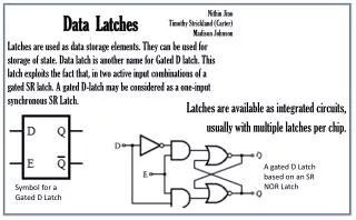
AND-INV Graphs with latches And-inverter graphs consist of vertices with two inputs – AND nodes – and edges between the nodes which may be complemented or not, denoted with a dot. Register inputs are represented as circuit outputs, and register outputs are represented as circuit inputs
The Programming Environment • OpenAccess is used to read in verilog files. • The FRAIG package [Mishchenko 2005] is used to represent the AIG network. • The ISCAS89 benchmark suite is used for testing the program (so far only up to s400.v) • This is the benchmark used by Sapatnekar and Pan
Retiming: Terminology • We have a circuit graph G = (V, E, d, w) • A vertex v V corresponds to a functional element of the circuit. In our case this is an AND node • A set of edges E that each connect two vertices u and v • d(v) is the propagation delay through v. In our case, this is always one. • w(e) is the weight of an edge, e. This is the number of registers on the directed edge.
Retiming Algorithm • Papaefthymiou’s is fast, but Pan’s c-retiming is better: • O((m+n)log(c/ε)), where m and n are the number of vertices and edges, c is the largest combinational delay and ε is the unit size for binary search • So the plan shifted to a retiming using continuous retiming
Pan’s C-Retiming Algorithm //Initialize the l_values for each node v in N do if (v is a PI) l(v) = 0; else l(v) = -; for each i = 0 to |U| + 2 done = true; for each non-PI node vj in N do tmp = maxe: u vj { l(u) – w(e) + d(vj) / } if ( vj is a PO and tmp > 1 ) return failure; if (l(vj) < tmp ) l(vj) = tmp; done = false; if (done == true ) return success; // c-retiming reached a fixed point return failure;
Pan’s C-Retiming Algorithm • The l-value is the longest path from the PIs to v • l(v) = max(l(u) –φ.w(u,v) + d(u,v) + d(v)) • This is also called the Sequential Arrival Time (SAT) • Since the delay of each node is always 1, the delay does not need to be calculated or looked up depending on the gate type • The weight of each edge never needs to be calculated. One clock period is subtracted from the l-value as it is propagated from the input of a register to the output of the register
C-Retiming adapted to FRAIGs // Initialize l_values for each node v in N do if (v is a PI) l(v) = 0; else l(v) = -; // perform iterative computation for all nodes in AIG network in topological order { tmp = maxe: u vj { l(u) +1 } if (l(vj) < tmp ) l(vj) = tmp; done = false; } // For each PO, if l_value > clock period, return failure // transfer the l_values from the register inputs to register outputs, // while subtracting the clock period // while there is no convergence, repeat iterative computation
Minimum Clock Period • To find the minimum clock period, a binary search is used pHi = largest combinational delay pLo = smallest combinational delay While( pHi – pLo > EPSILON ){ φ = (pHi + pLo)/2 if( retime(φ) == true ) pHi = φ else pLo = φ }
Converting l_values to a Retiming Now we have these l_values, how do we do the retiming? If we have two nodes v1 and v2, then the number of latches to add on that edge is just r(v2)-r(v1) v1 v2
Results • For ISCAS89 benchmark file s400 (173 Nodes) • Only 4 iterations were required for the retiming to converge • the retiming is very fast (less than 1 second) • depends on EPSILON • Still to do and future work: • Measure the timing for larger benchmarks (convert to OpenAccess friendly format) • Make the program faster • Use actual combinational delay instead of total number of nodes • Use Alan’s new Fraig package which is much faster • Use Howard’s algorithm or ASTRA instead of binary search
Conclusions • Implemented an efficient retiming algorithm for the Fraig package • More experimental timing results for large circuits soon to come
References • Cabodi et al. Optimizing Sequential Verification by Retiming Transformations, Design Automation Conference 2000 • M. C. Papaefthymiou. Understanding retiming through maximum average-delay cycles. Mathematical Systems Theory, 27, 1994, pp. 65-84. • A. Mishchenko, S. Chatterjee, R. Jiang, R. Brayton. FRAIGs: A Unifying Representation for Logic Synthesis and Verification. Submitted to DAC ’05. • A. Kuehlmann, M. Ganai, and V. Paruthi. Circuit-based Boolean Reasoning. Proceedings of the Design Automation Conference (DAC'01), Las Vegas, NV, June 2001, pp. 232-237. • Dasdan, A. Experimental analysis of the fastest optimum cycle ratio and mean algorithms. Tech. Rep. 2001-10-22-01, Synopsys, Inc., Oct. 2001.
References • J. B. Orlin and R. K. Ahuja. New scaling algorithms for the assignment and minimum cycle mean problem. Technical Report 2019-88, MIT Sloan School of Management,1988. • H. N. Gabow and R. E. Tarjan. Faster scaling algorithms for network problems. SIAM J. Computing, October 1989. • P. Pan. Continuous retiming: Algorithms and applications. In Proc IEEE Int. Conf. on Computer Design, pages 116-121, 1997