Download
1 / 20
430 likes | 972 Views
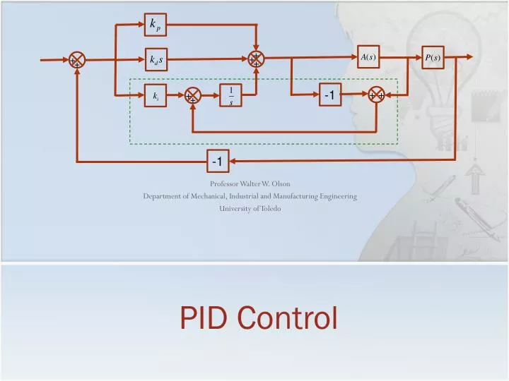
PID Control. Professor Walter W. Olson Department of Mechanical, Industrial and Manufacturing Engineering University of Toledo. +. -1. +. +. +. +. +. +. +. +. -1. Outline of Today’s Lecture. Review Ideal PID Controller Proportional Control Proportional-Integral Control

E N D
PID Control Professor Walter W. Olson Department of Mechanical, Industrial and Manufacturing Engineering University of Toledo + -1 + + + + + + + + -1
Outline of Today’s Lecture • Review • Ideal PID Controller • Proportional Control • Proportional-Integral Control • Proportional-Integral Derivative Control • Ziegler Nichols Tuning • PID Theory • Integrator Windup • Noise Improvement
Proportional-Integral-DerivativeController Based on a survey of over eleven thousand controllers in the refining, chemicals and pulp and paper industries, 97% of regulatory controllers utilize PID feedback. L. Desborough and R. Miller, 2002 [DM02]. • PID Control, originally developed in 1890’s in the form of motor governors, which were manually adjusted • The first theory of PID Control was published by a Russian (Minorsky) who was working for the US Navy in 1922 • The first papers regarding tuning appeared in the early 1940’s • Today. there are several hundred different rules for tuning PID controllers (See Dwyer, 2003, who has cataloged the major methods) • While most of the discussion is about the “ideal” PID controller, there are many forms of the PID controller
PID Control • Advantages • Process independent • The best controller where the specifics of the process can not be modeled • Leads to a “reasonable” solution when tuned for most situations • Inexpensive: Most of the modern controllers are PID • Can be tuned without a great amount of experience required • Disadvantages • Not optimal for the problems • Can be unstable unless tuned properly • Not dependent on the process • Hunting (oscillation about an operating point) • Derivative noise amplification
The Ideal PID Controller • The input/output realtionship for the PID Controller is the Integral-Differential Equation • The ideal PID controller has the transfer function • Structurally it would look like + + + + + -1
Proportional Control Y(s) R(s) + + + + + -1
Proportional – Integral Controller • Most controllers using this technology are of this form: • This reacts to the system error and reduces it Y(s) R(s) + + + + + -1
PID Tuning • Tuning is the choosing of the parameters kd, ki, and kp, for a PID Controller • The oldest and most used method of tuning are the Ziegler-Nichols (ZN) methods developed in the 1940’s. • The first method is based on the assumption that the process without its feedback loop performs with a 1st order transfer function, perhaps with a transport delay • The second method assumes that a higher order system has dominant poles which can be excited by gain to the point of steady oscillation • In order to establish the constants for computing the parameters simple tests are performed of the process
Ziegler-Nichols PID Tuning Method 1 for First Order Systems • A system with a transfer function of the formhas the time response to a unit step input: • This response might also be generated from a higher order system that is has high damping.
Ziegler-Nichols PID Tuning Method 1 for First Order Systems • The advice given is to draw a line tangent to the response curve through the inflection point of the curve. • However, a mathematical first order response doesn’t have a point of inflection as it is of the form (at no place does the 2nd derivative change sign.) My advice: place the line tangent to the initial curve slope • You also have to adjust for the gain K of the system by multiplying compensator by 1/K Rise Time T Lag L
Ziegler-Nichols PID TuningMethod 2 for Unknown Oscillatory System • The form of the transfer function unknown but the system can be put in steady oscillation by increasing the gain: • Increase gain,K, on closed loop system until the gain at steady oscillation, Kcr, is found • Then measure the critical period, Pcr • Apply table for controller constants and multiply by system gain 1/K 1 Cycle Pcr
PID: A Little Theory • Consider a 1st order function where the 1st method of Ziegler Nichols applies • The general transfer function for this system is • The term is the transport lag and delays the action for t0 seconds. Therefore • The term Ta is the time constant for the system. T measured on the graph is an estimate of this.
PID: A Little Theory • The method 1 PI controller applied to the loop equation is
PID: A Little Theory • In Method 2, the gain was increased until the system was nearly a perfect oscillatory system. • Since the gain changes the oscillatory patterns, the lowest order system that this could represent would by a 3rd order system. • For this system to oscillate, there must be a solution of the characteristic function for K real and positive where s=±wi
PID: A Little Theory • Applying the PI Controller:
Integrator Windup • We have tacitly assumed that the controlled devices could meet the demands of the controls that we designed. • However real devices have limitations that may prevent the system from responding adequately to the control signal • When this occurs with an integrating controller, the error which is used to amplify the control signal may build up and saturate the controller. • We refer to this as “integrator windup”: • the system can’t respond and the integrator signal is extremely large (often maxed out on a real controller) • the result is an uncontrolled system that can not return to normal operating conditions until the controller is reset
Integrator Windup • To avoid windup, a possible solution is to provide a correcting error from the actuator by adding another loop:(the actuator has to be extracted from the plant) + -1 + + + + + + + + -1
Derivative Noise Improvement • A major problem with using the derivative part of the PID controller that the derivative has the effect of amplifying the high frequency components which, for most systems, is likely to be noise. Without PID With PID
Derivative Noise Improvement • One way to improve the noise rejection at higher frequencies is to apply a second order filter that passes low frequency and rejects high frequency • The natural frequency of the filter should be chosen aswith N chosen to give the controller the bandwidth necessary, usually in the range of 2 to 20 • The controller then has the design
Summary • PID Theory • Integrator Windup • Noise Improvement Next Class Loop Shaping