Download
1 / 27
350 likes | 826 Views
PID Control. Professor Walter W. Olson Department of Mechanical, Industrial and Manufacturing Engineering University of Toledo. Outline of Today’s Lecture. Review Margins from Nyquist Plots Margins from Bode Plot Non Minimum Phase Systems Ideal PID Controller Proportional Control

E N D
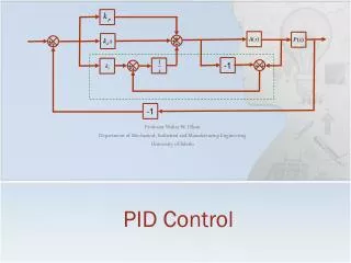
PID Control Professor Walter W. Olson Department of Mechanical, Industrial and Manufacturing Engineering University of Toledo
Outline of Today’s Lecture • Review • Margins from Nyquist Plots • Margins from Bode Plot • Non Minimum Phase Systems • Ideal PID Controller • Proportional Control • Proportional-Integral Control • Proportional-Integral Derivative Control • Ziegler Nichols Tuning
Margins • Margins are the range from the current system design to the edge of instability. We will determine • Gain Margin • How much can gain be increased? • Formally: the smallest multiple amount the gain can be increased before the closed loop response is unstable. • Phase Margin • How much further can the phase be shifted? • Formally: the smallest amount the phase can be increased before the closed loop response is unstable. • Stability Margin • How far is the the system from the critical point?
Gain and Phase Margin DefinitionBode Plots Magnitude, dB 0 Positive Gain Margin w Phase, deg -180 Phase Margin w Phase Crossover Frequency
Stability Margin • It is possible for a system to have relatively large gain and phase margins, yet be relatively unstable. Stability margin, sm
Non-Minimum Phase Systems • Non minimum phase systems are those systems which have poles on the right hand side of the plane: they have positive real parts. • This terminology comes from a phase shift with sinusoidal inputs • Consider the transfer functions • The magnitude plots of a Bode diagram are exactly the same but the phase has a major difference:
Another Non Minimum Phase SystemA Delay • Delays are modeled by the function which multiplies the T.F.
Proportional-Integral-DerivativeController Based on a survey of over eleven thousand controllers in the refining, chemicals and pulp and paper industries, 97% of regulatory controllers utilize PID feedback. L. Desborough and R. Miller, 2002 [DM02]. • PID Control, originally developed in 1890’s in the form of motor governors, which were manually adjusted • The first theory of PID Control was published by a Russian (Minorsky) who was working for the US Navy in 1922 • The first papers regarding tuning appeared in the early 1940’s • Today. there are several hundred different rules for tuning PID controllers (See Dwyer, 2003, who has cataloged the major methods) • While most of the discussion is about the “ideal” PID controller, there are many forms of the PID controller
PID Control • Advantages • Process independent • The best controller where the specifics of the process can not be modeled • Leads to a “reasonable” solution when tuned for most situations • Inexpensive: Most of the modern controllers are PID • Can be tuned without a great amount of experience required • Disadvantages • Not optimal • Can be unstable unless tuned properly • Not dependent on the process • Hunting (oscillation about an operating point) • Derivative noise amplification
The Ideal PID Controller • The input/output realtionship for the PID Controller is the Integral-Differential Equation • The ideal PID controller has the transfer function • Structurally it would look like + + + - +
The Ideal PID Controller • The system transfer function is + + + - +
Proportional Control Y(s) R(s) + + + - +
Proportional Controller kp=7.2
Proportional Controller • With kp=7.2, • We could reduce the error with a prefilter: } Error Also: the response time is poor + + + + + Y(s)=a(s) R(s) 0.139 -1
Proportional – Integral Controller • Most controllers using this technology are of this form: • This reacts to the system error and reduces it Y(s) R(s) + + + - +
Proportion-Integral Control • Applying PI control to the F-16 Elevator, Response time improved with no error
Proportional- Integral-DerivativeControl • The derivative component is rarely used. • Reduces overshoot • May slows the response time depending on the system • Sensitive to noise • For the F-16 Elevator
PID Tuning • Tuning is the choosing of the parameters kd, ki, and kp, for a PID Controller • The oldest and most used method of tuning are the Ziegler-Nichols (ZN) methods developed in the 1940’s. • The first method is based on the assumption that the process without its feedback loop performs with a 1st order transfer function, perhaps with a transport delay • The second method assumes that a higher order system has dominant poles which can be excited by gain to the point of steady oscillation • In order to establish the constants for computing the parameters simple tests are performed of the process
Ziegler-Nichols PID Tuning Method 1 for First Order Systems • A system with a transfer function of the formhas the time response to a unit step input: • This response might also be generated from a higher order system that is has high damping.
Ziegler-Nichols PID Tuning Method 1 for First Order Systems • The advice given is to draw a line tangent to the response curve through the inflection point of the curve. • However, a mathematical first order response doesn’t have a point of inflection as it is of the form (at no place does the 2nd derivative change sign.) My advice: place the line tangent to the initial curve slope • Adjust the gain K of the system by multiplying compensator by 1/K Rise Time T Lag L
Ziegler-Nichols PID Tuning Method 1 for First Order Systems • For this example, Rise Time T Lag L
Ziegler-Nichols PID TuningMethod 2 for Unknown Oscillatory System • The form of the transfer function unknown but the system can be put in steady oscillation by increasing the gain: • Increase gain, K, on closed loop system until the gain at steady oscillation, Kcr, is found • Then measure the critical period, Pcr • Apply table for controller constants and multiply by system gain 1/K 1 Cycle Pcr
Ziegler-Nichols PID TuningMethod 2 Example k=1000 k=1500 k=1750 k=2000 1 Cycle Pcr 17.8 Kcr=1875 1.0
Ziegler-Nichols PID TuningMethod 2 Example 1 Cycle Pcr 17.8 Kcr=1875 1.0
Summary • Ideal PID Controller • Proportional Control • Proportional-Integral Control • Proportional-Integral Derivative Control • Ziegler-Nichols Tuning Next Class: PID Controls Continued