Download
1 / 17

E N D
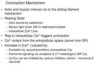
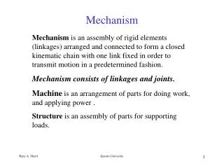
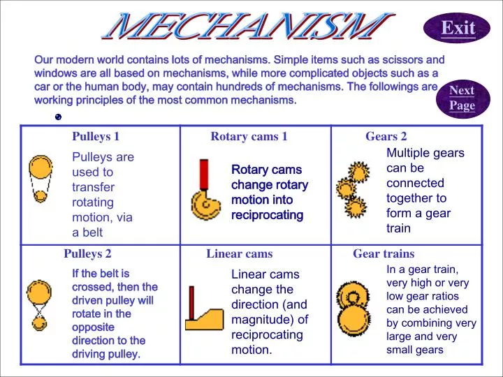
MECHANISM Exit Our modern world contains lots of mechanisms. Simple items such as scissors and windows are all based on mechanisms, while more complicated objects such as a car or the human body, may contain hundreds of mechanisms. The followings are working principles of the most common mechanisms. Next Page Pulleys 1 Rotary cams 1 Gears 2 Multiple gears can be connected together to form a gear train Pulleys are used to transfer rotating motion, via a belt Rotary cams change rotary motion into reciprocating Pulleys 2 Linear cams Gear trains In a gear train, very high or very low gear ratios can be achieved by combining very large and very small gears If the belt is crossed, then the driven pulley will rotate in the opposite direction to the driving pulley. Linear cams change the direction (and magnitude) of reciprocating motion.
Back Eccentrics a circular cam rotating about a point offset from its center Rack & pinion Crank & slider The rack and pinion gear is used to convert between rotary and linear motion A crank and slider mechanism changes rotary to reciprocal motion or vice versa,e.g. in the car engine. Quick return Glossary Mechanisms LINEAR MOTION ROTARY MOTION RECIPROCATING MOTION OSCILLATING MOTION EQUILIBRIUM FULCRUM LINKAGES quick return mechanism converts rotary motion into reciprocating motion Exit Revisions
Back Mechanisms: Pulleys Pulleys are used to transfer rotating motion, via a belt, from one shaft to another. The vacuum cleaner uses a pulley to transmit power from the electric motor to the rotating brushes. If both pulleys are the same diameter, then they will both rotate at the same speed. If one pulley is larger than another then mechanical advantage and velocity ratio are introduced. A large drive pulley will cause a smaller driven pulley to rotate faster.
Back Mechanisms: Pulleys If the belt is crossed, then the driven pulley will rotate in the opposite direction to the driving pulley. The velocity ratio of a pulley system is given by dividing the diameter of the driven pulley by the diameter of the driving pulley. Sometimes the pulleys and the belt are toothed to help prevent slippage. The sprocket and chain arrangement (as found on bicycles) is effectively a pulley system that can withstand very high loads without slippage.
Back Mechanisms: Crank and Slider A crank and slider mechanism changes rotary to reciprocal motion or vice versa. In the car engine (illustrated) the reciprocating motion of the piston caused by exploding fuel is converted into rotary motion as the con-rod moves the crankshaft around. An air compressor uses this principal in reverse - an electric motor turns the crankshaft and the piston moves up and down to compress the air
Back Mechanisms: Quick return mechanism The 'Whitworth' quick return mechanism converts rotary motion into reciprocating motion, but unlike the crank and slider, the forward reciprocating motion is at a different rate to the backward stroke. At the bottom of the slotted arm, the peg only has to move through a few degrees to sweep the arm from left to right, but it takes the remainder of the revolution to bring the arm back. This mechanism is most commonly seen as the drive for a shaping machine.
Back Mechanisms: Rotary Cams There are several different types of cam but most of these can be placed into two groups - rotary and linear. Rotary cams change rotary motion into reciprocating (backwards and forwards) motion. As the cam rotates, the follower moves accordingly. The exact distance it moves depends on the shape of the cam.
Back Mechanisms: Rotary Cams The protrusions on a cam are called lobes. The cams in a car engine have a single lobe - they will move the follower up and down only once per revolution. The square cam illustrated has four lobes, and hence lifts the follower four times per revolution.
Back Mechanisms: Eccentrics Cams with complicated profiles (the technical term for the shape of a cam) can be complicated to manufacture, particularly with the type of equipment available in the school workshop. However, if all you want to do is produce a single up and down motion for every revolution on the cam, a circular cam rotating about a point offset from its centre (an eccentric), will often suffice. Note that the cam follower need not just move up and down - it can be a lever as illustrated.
Back Mechanisms: Linear Cams Linear cams change the direction (and magnitude) of reciprocating motion. Unlike rotary cams, the linear cam moves backwards and forwards in a reciprocating motion and the shape of the surface of the cam determines how far the follower moves.
Back Mechanisms: Gears Multiple gears can be connected together to form a gear train. If there are an odd number of gears, the output rotation will be the same direction as the input. If there are an even number, the output will rotate in the opposite direction to the input. Note that for the simple type of gear train shown, the number of teeth on the intermediate gears does not affect the overall velocity ratio which is governed purely by the number of teeth on the first and last cog.
Back Mechanisms: Gear trains In a simple gear train, very high or very low gear ratios can only be acheived by combining very large and very small cogs. More complex 'compound' gear trains can be used to achieve high and low gear ratios in a compact space by coupling large and small cogs on the same axle - in this way, gear ratios of adjacent cogs can be multiplied through the gear train.
Back Mechanisms: Rack and Pinion The rack and pinion gear is used to convert between rotary and linear motion. Often the pinion rotates in a fixed position and the rack is free to move - this arrangement is used in the steering mechanism of most cars. Alternatively, the rack may be fixed and the pinion rotates moving up and down the rack. This latter arrangement (illustrated) is used as the drive mechanism for funicular railways (steep railways up the side of hills).
Back Mechanisms: Glossary LINEAR MOTION - motion in a straight line eg. the motion of a trainROTARY MOTION - circular motion eg. the motion of a bicycle wheelRECIPROCATING MOTION - repeating backwards and forwards motion eg. the motion of a piston in a car engineOSCILLATING MOTION - repeating forwards and backwards circular motion eg. the motion of a clock pendulumEQUILIBRIUM - a state of balance when both sides are equalFULCRUM - pivot, a point about which things rotateLINKAGES - two or more levers connected to produce a desired motion Next Page Exit
Back Revision Q.1 Cam rotates while ___________ moves accordingly. A. follower B. screw Q.2 Driven pulley rotates in opposite direction to driving pulley in _________________ system. A. Crossed belt B. pump Q.3 In a three-gear-train, the output rotation is in ____________ direction to the input. A. same B. opposite Exit References : animation & image from http://www.dtonline.org