Download
1 / 56
831 likes | 1.96k Views
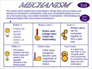
Mechanism. Machines are mechanical devices used to accomplish work. A mechanism is a heart of a machine. It is the mechanical portion of the machine that has the function of transferring motion and forces from a power source to an output.

E N D
Mechanism Machines are mechanical devices used to accomplish work. A mechanism is a heart of a machine. It is the mechanical portion of the machine that has the function of transferring motion and forces from a power source to an output. Mechanism is a system of rigid elements (linkages) arranged and connected to transmit motion in a predetermined fashion. Mechanism consists of linkages and joints. UC Berkeley
Can crusher Simple press Rear-window wiper Example of Mechanism UC Berkeley
Moves packages from an assembly bench to a conveyor Microwave carrier to assist people on wheelchair Lift platform Example of Mechanisms UC Berkeley
Lift platform Front loader Device to close the top flap of boxes Example of Mechanisms UC Berkeley
Rowing type exercise machine Conceptual design for an exercise machine Example of Mechanisms UC Berkeley
Example of Mechanisms Extension position Flexed position Six-bar linkage prosthetic knee mechanism UC Berkeley
Four-Bar Linkage UC Berkeley
Four-Bar Linkage Categories UC Berkeley
Four-Bar Linkage Categories UC Berkeley
4-Bar mechanisms UC Berkeley
S + l > p + q 4-Bar mechanisms 4 double rocker mechanisms UC Berkeley
The Slider-Crank Mechanism UC Berkeley
The Slider-Crank Mechanism UC Berkeley
Slider-Crank Mechanism - Inversion UC Berkeley
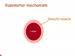
Function Generation Mechanisms A function generator is a linkage in which the relative motion between links connected to the ground is of interest. Mechanism Categories A four-bar hand actuated wheelchair brake mechanism UC Berkeley
Mechanism Categories Function Generation Mechanisms A four-bar drive linkage for a lawn sprinkler UC Berkeley
Mechanism Categories Motion Generation Mechanisms In motion generation, the entire motion of the coupler link is of interest (rigid body guidance). New Rollerblade brake system UC Berkeley
Mechanism Categories Motion Generation Mechanisms Four-bar automobile hood linkage design UC Berkeley
Mechanism Categories Path Generation Mechanisms In path generation, we are concerned only with the path of a tracer point and not with the motion (rotation) of the coupler link. Crane – straight line motion UC Berkeley
Primary Joints UC Berkeley
Higher Order Joints UC Berkeley
Motion Generation Mechanisms Moving a storage bin from an accessible position to a stored position Rotating a monitor into a storage position UC Berkeley
Motion Generation Mechanisms Moving a trash pan from the floor up over a trash bin and into a dump position Lifting a boat out of water UC Berkeley
Function Generation MechanismsGraphical Solution Two position synthesis – Design a four-bar crank and rocker mechanism to give 45o of rocker rotation with equal time forward and back, from a constant speed motor input. 1 – Draw the rocker O4B in both extreme positions, B1and B2 in any convenient location with angle θ4 = 45o. 2 – select a convenient point O2 on line B1B2 extended. 3 – Bisect line B1B2 , and draw a circle with that radius about O2. 4 – Label the two intersection of the circle with B1B2 extended, A1 and A2. 5 – Measure O2A (crank, link2) and AB (coupler, link3). UC Berkeley
Function Generation MechanismsGraphical Solution UC Berkeley
Crank-Rocker Mechanism UC Berkeley
Motion Generation MechanismsGraphical Solution Two position synthesis – C1D1 and C2D2 • Draw the link CD in its two desired positions, C1D1 and C2D2 • Connect C1 to C2 and D1 to D2. • Draw two lines perpendicular to C1 C2 and D1D2 at the midpoint (midnormals) • Select two fixed pivot points, O2 and O4, anywhere on the two midnormals. UC Berkeley
Motion Generation MechanismsGraphical Solution Two position synthesis (coupler output) – C1D1 and C2D2 The rigid body to be moved from position 1 to 2 is secured to link 3. UC Berkeley
Motion Generation MechanismsGraphical Solution Two position synthesis (coupler output) with Dyad added. 1 – Select any point B1 on link O2C1. Locate B2. 2 – Choose O6 anywhere on B1B2 extension. 3 – Draw a circle from O6 with radius B1B2/ 2. Mark the intersection with B1B2 extension as A1 and A2. UC Berkeley
Motion Generation MechanismsGraphical Solution Two position synthesis (coupler output) with Dyad added. UC Berkeley
Motion Generation MechanismsGraphical Solution Two position synthesis (rocker output) – C1D1 and C2D2 UC Berkeley
2 Position Motion – rocker output UC Berkeley
Motion Generation MechanismsGraphical Solution Three position synthesis – C1D1, C2D2andC3D3 • Draw the link CD in its three desired positions. • Follow the same procedure,draw construction lines, C1C2, C1C3 and C2C3. Same for point D. • Draw three midnormals for each point. • Locate the intersection of the three midnormal, O2 and O4 are the two fixed pivot points. UC Berkeley
Motion Generation MechanismsGraphical Solution Three position synthesis – C1D1, C2D2andC3D3 UC Berkeley
3 Position Motion UC Berkeley
3 Position Motion UC Berkeley
3 Position Motion UC Berkeley
Slider-Crank Mechanism The mechanism has a stroke B1B2 equal twice the crank length r2. Locations B1 and B2are called the extreme positions (limiting) of the slider In-line slider crank mechanism UC Berkeley
Slider-Crank Mechanism Offset slider-crank mechanism UC Berkeley
Straight line Mechanisms UC Berkeley
Straight Line Mechanism UC Berkeley
Scotch Yoke Mechanism UC Berkeley
Geneva Mechanism UC Berkeley
Linear Geneva Mechanism UC Berkeley
Ratchet Mechanism UC Berkeley
Straight Beam Walking Mechanism UC Berkeley
Roller and Flat Follower Cams UC Berkeley
Cylindrical Cam Mechanism UC Berkeley
Gears – Rack and Pinion UC Berkeley