Download
1 / 32
320 likes | 555 Views
Recent Progress with Atomic Layer Deposition. T.Proslier 1,2 , J.Norem 1 M.Pellin 3 , J.Zasadzinski 2 , J.Elam 4 , P.Kneisel 5 , R.Rimmer 5 , L.Cooley 6 , C.Antoine 7 High Energy Physics, ANL Department of Biological, Chemical and Physical Sciences, IIT Materials Science Division, ANL

E N D
Recent Progress with Atomic Layer Deposition T.Proslier1,2, J.Norem1 M.Pellin3, J.Zasadzinski2, J.Elam4, P.Kneisel5, R.Rimmer5,L.Cooley6, C.Antoine7 High Energy Physics, ANL Department of Biological, Chemical and Physical Sciences, IIT Materials Science Division, ANL Energy System Division, ANL J-Lab Technical Division, FNAL 7. CEA, France LDRD review 2009 Fermilab Workshop 09
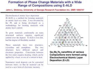
Higher-TcSC: NbN, Nb3Sn, etc Nb, Pb Insulating layers Can the fundamental properties of SRF Materials be enhanced? AG, Appl. Phys. Lett. 88, 012511 (2006) Multilayer coating of SC cavities: alternating SC and insulating layers with d < Higher Tc thin layers provide magnetic screening of the bulk SC cavity (Nb, Pb) without vortex penetration For NbN films with d = 20 nm, the rf field can be as high as 4.2 T ! No open ends for the cavity geometry to prevent flux leaks in the insulating layers Fermilab Workshop 09
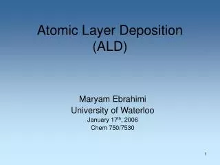
H0 = 324mT Hi = 150mT d A Simple Test? A Nb cavity coated by a single Nb3Sn layer of thickness d = 50nm and an insulator layer in between If the Nb cavity can withstand Hi = 150mT, then the external field can be as high as Lower critical field for the Nb3Sn layer with d = 50 nm and = 3nm: Hc1 = 1.4T is much higher than H0 A single layer coating more than doubles the breakdown field with no vortex penetration, enabling Eacc 100 MV/m LDRD review 2009 Fermilab Workshop 09
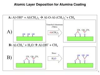
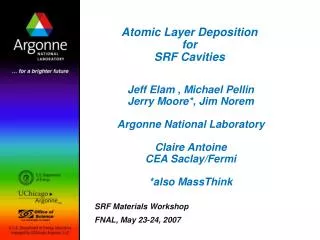
Ellipsometry Atomic Force Microscopy 4000 3500 3000 2500 Thickness (Å) 2000 1500 1000 Seagate, Stephen Ferro 500 0 • RMS Roughness = 4 Å (3000 Cycles) • ALD Films Flat, Pinhole free 0 500 1000 1500 2000 2500 3000 Flat, Pinhole-Free Film AB Cycles • Film growth is linear with AB Cycles ALD Reaction Scheme • ALD involves the use of a pair of reagents. • each reacts with the surface completely • each will not react with itself • This setup eliminates line of site requirments • Application of this AB Scheme • Reforms the surface • Adds precisely 1 monolayer • Pulsed Valves allow atomic layer precision in growth • Viscous flow (~1 torr) allows rapid growth • ~1 mm / 1-4 hours • No uniform line of sight requirement! • Errors do not accumulate with film thickness. • Fast! ( mm’s in 1-3 hrs ) • Pinholes seem to be removed. • Bulk LDRD review 2009 Fermilab Workshop 09
Mass Spectrometer • Reaction Product • CH4 Observed CH4 Signal (AU) In Situ Measurements During Al2O3 ALD TMA / H2O Al2O3 + CH4 Quartz Crystal Microbalance • Growth Occurs • in Discrete • Steps Al2O3 Thickness (Å) Fermilab Workshop 09
Mixed Layer Growth • Layer by Layer • note “steps” • atomic layer sequence “digitally” controlled ZnO [(CH3CH2)2Zn // H2O] [(CH3)3Al // H2O] Al2O3 ZnO Al2O3 • Mixed Layers w/ atomic precision • Low Temperature Growth • Transparent • Uniform • Even particles in pores can be coated. 100 nm • Films Have Tunable Resistivity, Refractive Index, Surface Roughness, etc. Mixed Oxide Deposition: Layer by Layer LDRD review 2009
ALD Thin Film Materials LDRD review 2009
Figure 3: Scanning Electron Microscope images of nearly atomically-sharp tips, before and after coating with a total of 35nm of material by ALD. The tip, initially about 4 nm, has been rounded to 35nm radius of curvature by growth of an ALD film. Rough surfaces are inherently smoothed by the process of conformal coating. Conformal Coating Removes Field Induced Breakdown • Synthetic Development Needed • Radius of Curvature of all asperities • (when polishing is not enough) • ALD can reduce field emission! • Could allow separation of superconductor and cavity support materials • (allowing increased thermal load, better mechanical stability) Normal conducting systems ( m cooling, CLIC ) can also benefit. • ~100 nm smooth coatings should eliminate breakdown sites in NCRF. • Copper is a hard material to deposit, and it may be necessary to studyother materials and alloys. Some R&D is required. This is underway. • The concept couldn’t be simpler. Should work at all frequencies, can be in-situ. LDRD review 2009 Fermilab Workshop 09
Flow Flow Components of thermal ALD System Ar, N2 Precursors Gas Switching Valves Carrier Gas H2O TMA Heated Substrates N2 Reaction Chamber Heaters Pump For cavities: the chamber is the cavity! New cavity dedicated system: controlling the outside atmosphere and High Temp. Fermilab Workshop 09
ANL thermal ALD facilities • 10 chemical precursor channels • gas, liquid, or solid • precursor temperature to 300C • ozone generator • Reaction temperature to 500 C • In-situ measurements • thickness (quartz microbalance) • gas analysis (mass spectrometer) • Coat flat substrates (Si), porous membranes, powders, etc.
Argonne ALD facilities: Plasma ALD (PEALD) Elemental Metals: Al, Cu, W, Mo… & alloys: NbN, TiN, Pt/Ir etc… Purer materials-> bulk properties
Niobium surfaces are complex Inclusions, Hydride precipitates Surface oxide Nb2O55-10 nm Residue from chemical processing 50 nm RF depth Interface: sub oxides NbO, NbO2 often not crystalline (niobium-oxygen “slush”) Interstitials dissolved in niobium (mainly O, some C, N, H) e- flow only in the top 50 nm of the superconductor in SCRF cavities!!! Clean niobium Grain boundaries LDRD review 2009 Fermilab Workshop 09
XPS - a Surface Probe of Nb Oxidation Dielectric Nb2O5 Nb2O5-, NbO2+are magnetic NbOx (0.2 < x < 2) is Metallic NbOx precipitates (0.02 < x < 0.2) Nb2O5 NbOx Nb Nb samples supplied by FNAL! LDRD review 2009
Complex Oxide surface: Interactions Oxide-superconductivity-cavity performance • Point contact spectroscopy: local probe the superconductivity at the surface • Magnetism-superconductivity • Quench mechanism • Raman spectroscopy: structure of the oxides • Damaged induced by HPR. Correlation with other techniques: XPS, SEM, EDX, EPR, SQUID, XRD… LDRD review 2009
PCT Tunneling Data Correlation of the local DOS with the low field Q Cavity-grade niobium single crystal (110)-electropolished 2 Ideal BCS, T~1.7K Baked Niobium 120C-24h Unbaked Niobium Average ZBC ratio = 1.6 Qo improvement 1.6 ILC-Single crystal cavities P.Kneisel T.Proslier, J.Zasadzinski, L.Cooley, M.Pellin et al. APL 92, 212505 (2008) LDRD review 2009
Fixing Niobium surfaces 2. ALD with 10 nm of Al2O3 1. Begin with EP, Clean, Tested Cavity 3. Add a low secondary electron emitter 4. Bake (>400 C) to “dissolve O into bulk LDRD review 2009 Fermilab Workshop 09
Al2O3(2nm) NbOx Nb Al2O3(2nm) Nb Solution to the Nb oxide problem: ALD + annealing in UHV Reference sample, DC sputtering Al2O3 Protective layer, diffusion barrier T=1.7 K Heating ->reduction + diffusion of the oxides Th.Proslier, J.Zasadzinski, M.Pellin et al. APL 93, 192504 LDRD review 2009
Cavity Experimental Plan • Obtain a Single Cell Cavity from JLab • “good” performance • Tested several times • Coat cavity with 10 nm’s Al2O3, 3 nm Nb2O5 • Niobia to reproduce original cavity surface • Dust, clean room care • Acceleration Test at J Lab • First test of ALD on cavities • Check for “stuck” dust, high pressure rinse difficulties, material incompatibilities, etc. • Goal: No performance loss • Bake @ retest still trying to finish LDRD review 2009
Cavities used for ALD Jlab has provided three different niobium cavities to ANL for atomic layer deposition: • Cavity 1: Material: RRR > 300 poly-crystalline Nb from Tokyo-Denkai Shape/frequency: Earlier KEK shape, 1300 MHz Baseline: electropolished, in-situ baked • Cavity 2 : Material: RRR > 300 large grain Nb from Tokyo-Denkai Shape/frequency: TESLA/ILC shape, 1300 MHz Baseline: BCP, in – situ baked • Cavity 3: Material: RRR > 300 poly-crystalline Nb from Fansteel Shape/Frequency: CEBAF shape, 1497 MHz Baseline: BCP only LDRD review 2009
J Lab Cavity 1: Best Previous Performance • Strong field emission for last 5 MV/m LDRD review 2009 Fermilab Workshop 09
J Lab Cavity1: Last Acceleration Test (Cluster Cleaning) • Cavity “as received” for ALD Cavity Treatment LDRD review 2009 Fermilab Workshop 09
J Lab Cavity1: After ALD Synthesis (10 nm Al2O3 + 3 nm Nb2O5) • Only last point shows detectable field emission. • 2nd test after 2nd high pressure rinse. (1st test showed field emission consistent with particulate contamination) LDRD review 2009 Fermilab Workshop 09
Baking 450 C/24hrs: LDRD review 2009 Fermilab Workshop 09
J lab Cavity 2: Large grain,10 nm Al2O3 + 3 nm Nb2O5 ALD2-Baseline First coating: 10 nm Al2O3 + 3 nm Nb2O5 Baseline Test 2 Test 1 Second coating: 5 nm Al2O3 + 15 nm Nb2O5 LDRD review 2009 Fermilab Workshop 09
J Lab Cavity 3: Small grain 2 steps Coating, 15 nm Al2O3 LDRD review 2009 Fermilab Workshop 09
J Lab Cavity 3Baking 450C/20hrs--Coating: 5nm Al2O3+15 nm Nb2O5 Second coating LDRD review 2009 Fermilab Workshop 09
HT baking: T maps and Rs(T) T-map at the highest field measured during the test after 120 °C, 23 h UHV bake. T-map at the highest field measured during the test after 450 °C, 20 h heat treatment Ohmic losses HT baking: Improve the super. properties Fermilab Workshop 09
Preliminary Conclusion • The ALD process shows promise, especially, if one thinks about multi-layer coatings to improve cavity performances as proposed by A. Gurevich. NbN layers are being produced now (though not of high quality). • However, as typical for SC cavity work, development of the process is necessary – there is no “magic” process, which immediately solves all problems • The appearance of multipacting in cavity 1 and 2 is a little bit concerning, but can be overcome by additional coating. Layers that are expected to be much better have not yet been tested (TiN for example). • Baking doesn’t improve cavity performance: cracks can appear due to strong Nb oxide reduction -> path for oxygen injection -> Ohmic losses need a in-situ baking + ALD coating set up. LDRD review 2009 Fermilab Workshop 09
New materials grown by thermal ALD. New precursor for Thermal ALD of Nb, NbN, Nb2O5 : H2O -> Nb2O5 + HF (gas) GR = 2 Å/cy (usual: 0.5 Å/cy) NbF5 + Si2H6 -> NbSi + SiHF3 (gas) GR = 4.2 Å/cy NH3 -> NbN + HF (gas) GR = 0.6 Å/cy (usual: 0.3/cy) Study metallic/ super. properties to optimize purity Purpose: Aluminum cavity + Nb by ALD (few microns)+ multilayer NbN/SiO2 future publication.J.Chem LDRD review 2009
Future of cavities at Argonne: • SRF project funded for 3 years • Plasma ALD system create new opportunities : • Plasma Etching to remove oxides • Deposition of pure metals and superconductors • Optimization of thin film superconducting properties: Multilayers Fermilab Workshop 09
High Pressure rinsing study: Nb Oxide peak HPR damaged Nb sample d~10×2.103 = 20 µm d=10 nm d=10 e LDRD review 2009
High Pressure rinsing study: Raman co-focusing: Z-axis mapping XPS, sputtering: depth profiling