Download
1 / 9
90 likes | 92 Views
Fatigue analysis and Optimization of connecting rod are the modern trend in automotive engineering industry emphasis on many parameters like total deformation, life, factor of safety, stress biaxiality and fatigue sensitivity. The main scope of this work comprises detailed review on various methods and procedures adopted by different researchers in Fatigue analysis of commercially used Engine Connecting rod. The objective of conducting fatigue analysis varies from each other like Weight reduction, Cost reduction, Shape optimization and fatigue life calculation at varying boundary conditions and loads. Fatigue analysis has a very dominant position in product design and development as more than 50 of the products, structural failures are due to fatigue concept only. The review have emphasized the importance of conducting the fatigue analysis of the connecting rod to identity its critical points, fatigue life and factor of safety etc., for its better performance and life period extension. N. Mohammed Raffic | Dr. K. Ganesh Babu | K. N. Arun Kumar "Design Evaluation and Optimization of IC Engine Connecting Rods A Review" Published in International Journal of Trend in Scientific Research and Development (ijtsrd), ISSN: 2456-6470, Volume-2 | Issue-3 , April 2018, URL: https://www.ijtsrd.com/papers/ijtsrd10814.pdf Paper URL: https://www.ijtsrd.com/engineering/mechanical-engineering/10814/design-evaluation-and-optimization-of-ic-engine-connecting-rods-u2013-a-review/n-mohammed-raffic<br>

E N D
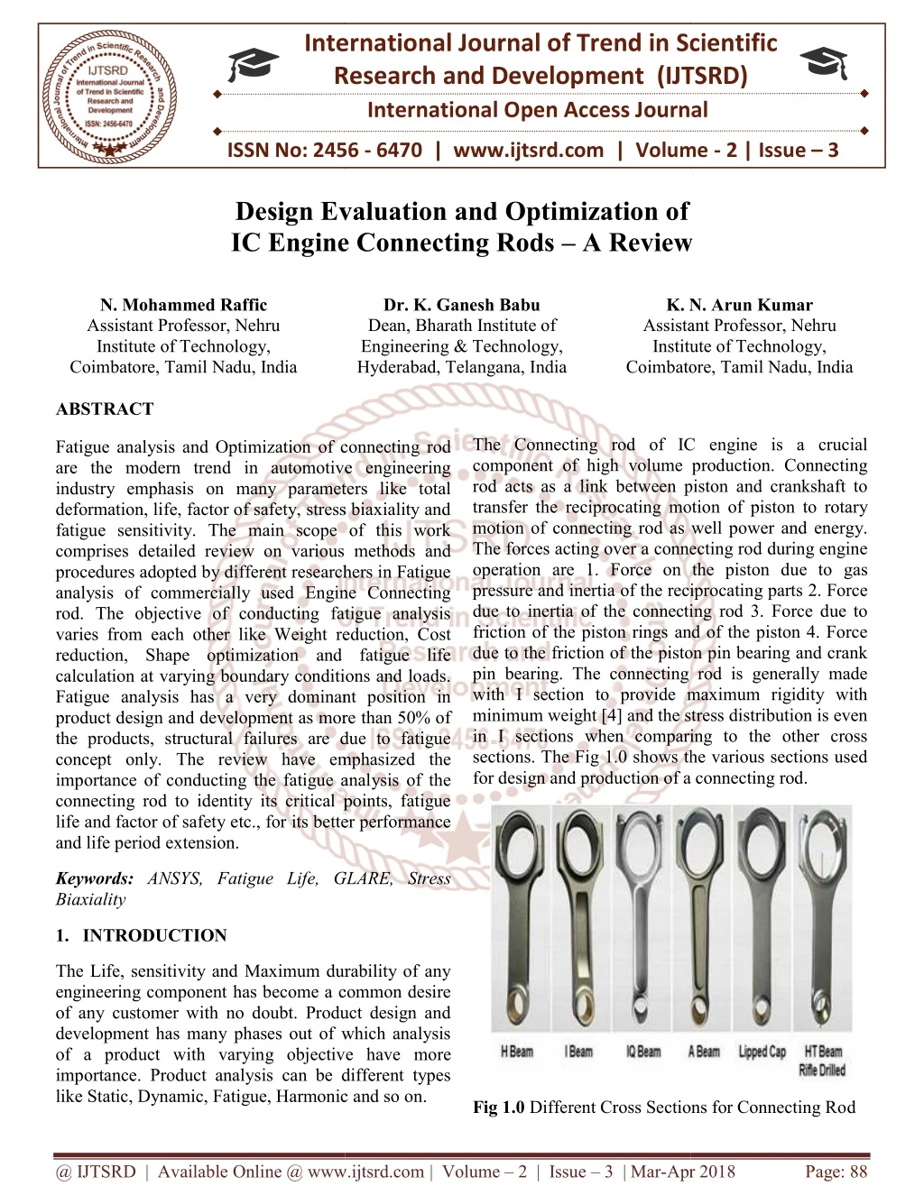
International Research Research and Development (IJTSRD) International Open Access Journal Design Evaluation and Optimization of Engine Connecting Rods – A Review International Journal of Trend in Scientific Scientific (IJTSRD) International Open Access Journal ISSN No: 2456 ISSN No: 2456 - 6470 | www.ijtsrd.com | Volume 6470 | www.ijtsrd.com | Volume - 2 | Issue – 3 Design Evaluation IC Engine Connecting Rods A Review N. Mohammed Raffic Assistant Professor, Nehru Institute of Technology, Coimbatore, Tamil Nadu, India ABSTRACT Fatigue analysis and Optimization of connecting rod are the modern trend in automotive engineering industry emphasis on many parameters like total deformation, life, factor of safety, stress biaxiality and fatigue sensitivity. The main scope of this work comprises detailed review on various methods and procedures adopted by different researchers in Fatigue analysis of commercially used Engine Connecting rod. The objective of conducting fatigue analysis varies from each other like Weight reduction, Cost reduction, Shape optimization and fatigue life calculation at varying boundary conditions and loads. Fatigue analysis has a very dominant position in product design and development as more than 50% of the products, structural failures are due to fatigue concept only. The review have emphasized the importance of conducting the fatigue analysis of the connecting rod to identity its critical points, fatigue life and factor of safety etc., for its better performance and life period extension. Dr. K. Ganesh Babu Dean, Bharath Institute of Engineering & Technology, Hyderabad, Telangana, India N. Arun Kumar Assistant Professor, Nehru Institute of Technology, K. N. Assistant Institute of Technology, Coimbatore, Coimbatore, Tamil Nadu, India The Connecting rod of IC engine is a crucial component of high volume production. Connecting rod acts as a link between piston and crankshaft to transfer the reciprocating motion of piston to rotary motion of connecting rod as well power and energy. The forces acting over a connecting rod during engine operation are 1. Force on the piston due to gas pressure and inertia of the reciprocating parts 2. Force due to inertia of the connecting rod 3. Force due to friction of the piston rings and of the piston 4. Force due to the friction of the piston pin bearing and crank pin bearing. The connecting rod is generally made with I section to provide maximum rigidity with minimum weight [4] and the stress distribution is even in I sections when comparing to the other cross sections. The Fig 1.0 shows the various sections used for design and production of a connecting rod. for design and production of a connecting rod. The Connecting rod of IC engine is a crucial component of high volume production. Connecting rod acts as a link between piston and crankshaft to ciprocating motion of piston to rotary motion of connecting rod as well power and energy. The forces acting over a connecting rod during engine operation are 1. Force on the piston due to gas pressure and inertia of the reciprocating parts 2. Force inertia of the connecting rod 3. Force due to friction of the piston rings and of the piston 4. Force due to the friction of the piston pin bearing and crank pin bearing. The connecting rod is generally made with I section to provide maximum rigidity with minimum weight [4] and the stress distribution is even in I sections when comparing to the other cross sections. The Fig 1.0 shows the various sections used analysis and Optimization of connecting rod are the modern trend in automotive engineering industry emphasis on many parameters like total deformation, life, factor of safety, stress biaxiality and fatigue sensitivity. The main scope of this work detailed review on various methods and procedures adopted by different researchers in Fatigue analysis of commercially used Engine Connecting rod. The objective of conducting fatigue analysis varies from each other like Weight reduction, Cost hape optimization and fatigue life calculation at varying boundary conditions and loads. Fatigue analysis has a very dominant position in product design and development as more than 50% of the products, structural failures are due to fatigue The review have emphasized the importance of conducting the fatigue analysis of the connecting rod to identity its critical points, fatigue life and factor of safety etc., for its better performance Keywords: ANSYS, Fatigue Life, GLARE, Stress Biaxiality GLARE, Stress 1.INTRODUCTION The Life, sensitivity and Maximum durability of any engineering component has become a common desire of any customer with no doubt. Product design and development has many phases out of which analysis of a product with varying objective have more importance. Product analysis can be different types like Static, Dynamic, Fatigue, Harmonic and so on. like Static, Dynamic, Fatigue, Harmonic and so on. The Life, sensitivity and Maximum durability of any engineering component has become a common desire of any customer with no doubt. Product design and development has many phases out of which analysis of a product with varying objective have more e. Product analysis can be different types Fig 1.0 Different Cross Sections for Connecting Ro Different Cross Sections for Connecting Rod @ IJTSRD | Available Online @ www.ijtsrd.com @ IJTSRD | Available Online @ www.ijtsrd.com | Volume – 2 | Issue – 3 | Mar-Apr Apr 2018 Page: 88
International Journal of Trend in Scientific Research and Development (IJTSRD) ISSN: 2456-6470 Fatigue analysis has a predominant position in engineering analysis as 50-90% of the components fail due to fatigue [5]. Fatigue may occur when a member is subjected to repeated cyclic loadings. Structures subjected to repeated cyclic loadings can undergo progressive damage which shows itself by the propagation of cracks. This damage is called fatigue and is represented by a loss of resistance with time. A number of factors influence the fatigue life of a component in service, viz., (i) complex stress cycles, (ii) engineering design, (iii) manufacturing and inspection, (iv) service conditions and environment and (v) material of construction [2].The authors have reported that the fatigue analysis can be classified in to three areas 1. Materials 2. Analysis and 3. Results evaluation. The Fig 2.0 shows an Optimized Connecting rod after Fatigue analysis [9]. compressive to find the maximum values of stress analysis output parameters which may provide a idea for fatigue analysis. The analysis have revealed the critical points of the connecting rod such as end of the shank and area near to piston pin hole (Point 46 in mesh) , lateral and inner face of crank end of the connecting rod and the end of the shank and near to crank hole. The fatigue analysis in conducted with stress concentration coefficient as 1.25 and factor of safety for a design life of 1,000,000 cycles. The authors have concluded that in order to improve the fatigue life of the connecting rod of tractors further the design life cycle may be increased by decreasing the value of stress concentration coefficient and the allowed number of cyclic loading on the connecting rod is found to be 108 cycles. Mohammad investigated the Fatigue Analysis of Connecting rod used in Samand Engine using FEM. In their work the authors have performed FEM analysis of Samand Engine Connecting Rod under maximum compression and tension loadings which are further considered for the evaluation of critical points in the connecting rod. Optimizing the Connecting Rod for durability based upon the fatigue life calculation and longevity analysis conducted using ANSYS was the major objective of their study. The authors have inputted the experimental data of Combustion chamber pressure curve obtained from Iran Khodro’s Power test lab to the mechanism modeled through MSc. ADAMS software. C70S6 steel was the material considered for Connecting rod. Solid 92 Element is considered for analyzing the Connecting rod model in ANSYS 9.0. The meshed model is subjected to four different rotational speeds such as 1000 RPM (slow rotational speed), 3000 RPM (middle rotational speed), 4500 RPM (maximum torque rotational speed) and 6000 RPM (maximum power rotational speed of engine). Through analysis from ANSYS the authors have reported that the maximum pressure stress of 297.361 MPa was obtained between the pin end and connecting rod linkage and the maximum tensile stress of 202.927 MPa was obtained at crank end of the connecting rod. The authors have reported that the lowest fatigue cycle equals 109 and the critical nodes were identified between pin end and connecting rod linkage. The authors have concluded that the Factor of Safety for pressure stress was obtained 3.363 and for tensile stress was obtained 4.927 and the results obtained were in good agreement with the past research reports. Ranjbarkohan et.al (2011) has Fig 2.0 Optimized Connecting Rod after Fatigue Analysis 2.LITERATURE REVIEW M.omid et.al (2008) has made an attempt to analyse the Connecting rod of Universal tractor (U650). The authors have given a clear idea about the fatigue analysis and it’s types in the introduction part of their research work. The authors have adopted continuum mechanics approach in their study for the fatigue crack initiation and Coffin – Manson method is adopted for the analysis in which the relation between the deformations (є) , stresses (σ) and number of loading cycles (N) are considered. The authors have considered the connecting rod with high strength alloy steel as the material and the maximum load that acts over the part will be 9500 N and it has been applied in the form of fully reversed loading which has no mean stress presence. The authors have meshed the connecting rod using 10-node tetrahedral element in ANSYS 7 as the element can provide the results with high degree of accuracy. The load was applied over the connecting rod in both the forms ie. Tensile and @ IJTSRD | Available Online @ www.ijtsrd.com | Volume – 2 | Issue – 3 | Mar-Apr 2018 Page: 89
International Journal of Trend in Scientific Research and Development (IJTSRD) ISSN: 2456-6470 Pushpendra Kumar Sharma et.al (2012) presented a report on Fatigue analysis and optimization of connecting rod using FEA. The authors have used PRO/E Wildfire 3.0 for modeling the connecting rod and forged steel was the material considered. In their study the authors have calculated the total deformation of the Connecting rod under static loading condition using ANSYS Workbench. Post to analysis of connecting rod for tensile loading the authors have observed the critical regions in the order of decreasing stress intensity are the oil hole, the surface of the pin end bore, the piston pin end transition, the extreme end of the cap and the crank end transition of the connecting rod. Moreover the authors have conducted fatigue analysis to obtain the outputs such as Fatigue life, damage, Factor of safety, Stress biaxiality, and Fatigue sensitivity. The major objective of the authors was to optimize the connecting rod based upon stress and fatigue analysis results. The authors have drawn a conclusion stating that the weight of the connecting rod by can be reduced to 20% by changing the material form forged steel to C-70 and they also reported that the ANSYS software provides an overview about the stress distribution in the part considered and provides a way for improving the strength of the part by hardening at selective regions. authors have concluded that weight of the connecting rod can be reduced by 5 gm from the existing design and the maximum stress is found near the piston end or the end of the shank. Yogesh. B. Dupare et.al (2014) carried out Fatigue analysis of connecting rod in ANSYS. In their work the authors have considered four stroke petrol engine to find the magnitude and location of stresses which have more susceptibility to undergo failure when loaded. The model of the part was created using PRO/E and the maximum load that is applied over the part is 4319 N comparatively low and the fully reversed loading is considered to create alternating stress cycles. The authors have stated that the purpose of conducting the fatigue test is to optimize the part. During their analysis the maximum and minimum equivalent alternating stress was 76.22 MPa and 0.01 MPa and the maximum and minimum biaxiality indications are 0.97 and -1.0. The authors have strongly concluded that fatigue strength was the design driving factor in the optimization of connecting rod and 20% reduction in weight can be achieved by considering the other factors like Static strength and buckling load. Gaba.Peeyush et.al (2014) reported the design evaluation of connecting rod using FEM for High Cycle Fatigue Strength (HCFS). In their work the authors have stated that during meshing of the connecting rod the areas where there is a sudden change in profile of the geometry, the radius the radius around the stem close to the big end and the transition radius of the bearing cap should be considered for fine mesh to get more accurate and quality results. In case of meshing the authors have considered three different cases for anlaysis. Surface elements with uniform size, Surface elements with uniform tetra mesh size along both depth and surface, Meshing with coarse pattern by reducing the no of elements from the previous two cases. In case of load analysis the bolt pretension force is the first step considered by authors to find the contact evaluation by taking the minimum value and by taking the maximum value for High Cycle Fatigue analysis as the high pretension can lead to a higher mean stress. The authors have considered a total of 6 different load cases for analysis and they are 1. Bolt preload 2. Mass forces at 1375 rpm 3. Mass forces at 3250 rpm (Rated speed) 4. Mass forces at 3600 rpm (Over speed) 5.Gas and mass forces at 1375 rpm 6. Gas and mass forces at 3250 rpm (Rated speed). Followed by those loading conditions the authors have additionally Om Parkash et.al (2013) has carried out both static and fatigue analysis of Universal Tractor U650 connecting rod in order to optimize the weight of the connecting rod comparing to the existing design. In their work the authors have modeled the part using CATIA V5R19 and analyzed the part using ANSYS Workbench by considering the properties of C-70 Alloy steel for material. In their analysis the axial load acting over the connecting rod due to gas pressure is taken as 9500N in the form of axial load is applied over the part by keeping the piston as fixed end and load applied at crank end and vice versa. Von mises stress, Total deformation and Elastic strain were the outputs obtained through static analysis. The authors have conducted fatigue Goodman theory for a life cycle of 109. Life, Biaxiality indication, Damage and safety factor were the output parameters considered for fatigue analysis. In case of Biaxiality indication the authors have considered ‘0’ as uniaxial stress, ‘-1’ as pure shear , ‘1’ as pure biaxial state. The authors have stated that the value more than 1 indicates that the part will undergo failure before the design life. Through different analysis procedures done for the part the analysis considering @ IJTSRD | Available Online @ www.ijtsrd.com | Volume – 2 | Issue – 3 | Mar-Apr 2018 Page: 90
International Journal of Trend in Scientific Research and Development (IJTSRD) ISSN: 2456-6470 considered two more load cases by combining them at 1375 rpm and 3250 rpm. C70S6 was the material considered for the part. The authors have calculated the mean and alternating stress, Factor of safety during analyzing the connecting rod. The required factor of safety for the material selected is found to be 1.50 but the analysis has given the F.O.S value as 1.71. Due to the various loading conditions followed in the analysis the part has shown different behavior. The authors have finally concluded that the geometry near the big eye end of the connecting rod need to get modified as the F.O.S value has fallen down at that point. The authors have also advised that the accuracy of the results are purely based upon the no of elements, type of elements used in analysis. compressive load at piston pin end and crank end restrained. The authors have stated the critical regions in the order of decreasing stress intensity are the oil hole, surface of the pin end bore, piston pin end transition, extreme end of the cap and crank end transition of the connecting rod. The authors have performed fatigue analysis by inserting a fatigue tool in ANSYS Workbench to evaluate the fatigue life , damage, F.O.S, stress biaxilaity and fatigue sensitivity. The objective of conducting the fatigue analysis is to optimize the connecting rod for its weight and manufacturing cost. The authors have tabulated the results of fatigue analysis and the maximum values of Life, Damage, safety factor, biaxiality indication and equivalent alternating stress are 1,000,000 , 1000 , 15.0 , 0.94 and 83.585 MPa. The authors have concluded that the weight of connecting rod by 7.9% (100 gms) from the existing one and by using materials such as micro-alloyed steels whose yield strength and endurance limit are higher the weight at the piston pin end and the crank end can be further reduced. The author has also advised to conduct Experimental Stress Analysis (ESA) to calculate the stresses and also to conduct a study on the effects of load on the connecting rod at dynamic conditions. Ramesh N.G (2014) has analyzed the 4 stroke single cylinder diesel engine connecting rod using FEA. The author has clearly stated the importance of fatigue analysis of mechanical components as fatigue failure is the prime cause for many part failures. The author have considered the properties of C-55 hardened and tempered steel for the connecting rod part. . The author have modeled the connecting rod using CATIA and meshed the model with tetrahedral element using ANSYS software. The author have made analytical calculations of the connecting rod and have found the load to be applied as axial force at the small end center of the connecting rod as 79454.37 N . The same load value is considered in both tension and compression. Through ANSYS the author has evaluated the stress as various locations of the connecting rod and the maximum stress value is found in the shank area of the connecting rod with 216.3 N/mm2. The author has conducted fatigue analysis of the connecting rod followed by static structural analysis by using the S-N theory to evaluate the fatigue life of the connecting rod. The fatigue life is evaluated by considering the Goodman diagram and a load of 79.45 KN is applied and the fatigue life is calculated till 107 cycles. The author has concluded that the compressive stress is maximum between the small end and shank of connecting rod and the Factor of safety is 1.34 and I sections is recommended by the author for the profile of the connecting rod as the stress distribution is uniform over the entire web of the connecting rod. Ambrish Tiwari et.al (2014) presented his detailed report about reducing the weight and cost for production of forged steel connecting rod. The connecting rod selected for study by the authors is a Mid size sedan supplied by OEM’s which comprises crank radius, piston diameter, the piston assembly mass, and the pressure-crank angle diagram . In their work the authors have mentioned two different works 1. Dynamic load, the stress induced and 2. Quasi- Dynamic stress analysis of connecting rod. The authors have performed fatigue study based on Stress Life (S/N) theory and modified Goodman diagram. The authors have made a study on Static FEA and Quasi Dynamic FEA in their work. The authors have determined the R-ratio, degree of stress multiaxiality by applying the maximum engine load as on extreme load and compressive load corresponding to the peak gas pressure as other extreme load. The analysis of the part is carried out using I-DEAS software by considering the crank angles at three different engine speeds i.e. 5700 rev/min, 4000 rev/min and 2000 rev/min respectively. The axial load component of load at the crank end or pin end was tensile and it was applied with a cosine distribution and the compressive load was applied with uniform distribution . The Dnyandeep K. Nikam et.al (2014) has done optimization and fatigue analysis of modified connecting rod using FEA tool. The authors have considered two different load cases where the loads and supports are same but axial tensile and @ IJTSRD | Available Online @ www.ijtsrd.com | Volume – 2 | Issue – 3 | Mar-Apr 2018 Page: 91
International Journal of Trend in Scientific Research and Development (IJTSRD) ISSN: 2456-6470 authors have tabulated the inputs to be applied in analysis for different engine speeds of varying crank angles . The model of the connecting rod was meshed with parabolic tetrahedral elements of varying lengths 2.5 mm (20719 Elements), 2mm (37373 Elements), 1.5mm (77316 Elements), and 1mm (224609 Elements). The authors have selected ten different locations for the convergence of Von mises stress for the applied load and plotted a graph between the element length and Von mises stress. Next to static analysis the authors have performed Quasi Static analysis of the part by considering a total 15 different locations in the part for convergence purpose. The authors have reported that the locations 12 and 13 about 87.6 mm from crank end center have shown high bending stress for global element length of 1.5 mm and 1mm as local element length. The author has made a comparison between the results obtained for static and quasi dynamic analysis and the same is being plotted as graph between crank angle (deg) and stress (MPa). A chart is prepared between various locations and Von mises stress for both tensile and compressive load. The authors have concluded the following form their analysis. bore, the stresses were observed to be significantly lower under conditions of assembly. 8. The optimized geometry of connecting rod is 10% lighter and of 25% lesser cost than the existing one. 9. The author has also proposed to use other fracture crackable materials such as micro - alloyed steel whose yield strength and endurance limit are higher for reducing weight and cost of connecting rod. Puran Singh et.al (2015) has analyzed the connecting rod made with cast iron for both Fatigue and Structural loading using FEA. The authors have clearly stated in their abstract that the axial compressive load is more than the axial tensile load and the design is only analyzed for compressive loads and continued with fatigue analysis. The authors have mentioned about the specifications of the connecting rod along with its material properties and the calculation of compressive force acting over the connecting rod is found to be 134377 N. The solid model is meshed by using ANSYS software and the compressive force is applied along the X axis direction. The authors have stated that the meshed models have 413465 elements and 511298 nodes. The meshed model was analysed to find out the various stress such as Maximum and Minimum values of Normal stress, principle stresses, von mises stress, and deformation along various axes. The results obtained from the analysis shows that the Maximum normal stress is about 227.03 MPa, Maximum principle stress is about 411.32 MPa, Maximum von mises stress is about 411.41 MPa and the maximum total deformation is about 0.042314 mm. The authors have concluded that the inner dead centre is the point where the maximum force is acting in the part and the compressive force plays a vital role in connecting rod analysis comparing to tensile force. 1. Considerable differences in structural behavior is found for both axial fatigue loading and dynamic loading. 2. Out of three engine speeds used in analysis the engine speed value 5700 rev/min may be considered for design and optimization and 360 degree crank angle. 3. The significant stress is bending stress and it varies depending upon the location. The tensile bending stress were 16% of stress amplitude, 19% of stress amplitude at the shank center and negligible at the piston end. 4. The value of R (minimum to maximum stress ratio) varies with respect to location of connecting rod and crank speed. Jitendra Jayant et.al (2015) presented the design and development of connecting rod with aluminum alloy replacing iron based alloy material for reciprocating piston engine. In their work the authors have considered the Connecting rod of four stroke petrol engine for analysis. The author has given the literature review of around 20 research papers in his work. The author has considered C-70 as part material and modeling is done by using PRO/E 4.0 and ANSYS Workbench 14.0 is used for analysis. The authors have described about the various manufacturing methods of connecting rod. The author has conducted static analysis of connecting rod with Von mises 5. As the stress multiaxiality is high, multiaxial fatigue analysis should be performed to find the fatigue strength. 6. By changing the material from forged steel to Crackable forged steel (C-70) 7. At locations like cap-rod outer edge, the extreme end of the cap, and the surface of the piston pin end @ IJTSRD | Available Online @ www.ijtsrd.com | Volume – 2 | Issue – 3 | Mar-Apr 2018 Page: 92
International Journal of Trend in Scientific Research and Development (IJTSRD) ISSN: 2456-6470 stress, Shear stress, Elastic strain and total deformation as output parameters. Based upon the results of Static FEA and load analysis the optimization study was conducted. The authors have performed fatigue analysis of the part whose output includes fatigue life, damage, factor of safety and stress biaxiality indication. The authors have concluded that the ideas proposed by various researchers from reference may be considered while designing a connecting rod for weight and cost reduction and increase in life time. Reinforced Epoxy) is fiber metal laminate composed of several thin layers of metal interlinked with glass fiber bonded together with a matrix such as epoxy and it was patented by Akzo Nobel in 1987. It finds applications in aircraft structures. In the present work the authors have coated GLARE on aluminum alloy with a thickness of 0.3mm. Solidworks 2015 and ANSYS 15.0 are the two software’s preferred by the authors for modeling and analysis. A load of 4500N was applied over the connecting rod to calculate the various outputs such as factor of safety, damage and biaxiality indication. The authors have observed that the F.O.S is maximum at cylindrical bolt head (15) and minimum at crank head (2.2371). The biaxiality indication is maximum at crank end with 0.99734 and minimum at piston end with -0.99992. The authors have finally concluded that the Connecting rod made with aluminum alloy coated with GLARE has shown better results when comparing to connecting rod made only with aluminum. The Connecting rod provided with GLARE coating have shown high factor of safety which denotes the long life of the connecting rod. Dipalee S. Bedse et.al (2015) has performed the design evaluation through Finite Element Analysis for fatigue life of Hero Honda Motor cycle 100 CC Engine connecting rod. In their work the authors have explained about the research gap found with their topic as most of the research work was done based upon heavy vehicle connecting rod and for light vehicle connecting rod very few research works were found. The authors have specified that the aim of their work is to study the existing system of connecting rod to find out the problem areas , different parameters such as stresses , deflection and fatigue failure of the connecting rod design a connecting rod based upon its fatigue life. The 3D model of the connecting rod is created using CATIA HYPERMESH. The structural strength of the connecting rod is assessed using UTM. By using standard formulas and equations the authors have calculated the pressure acting on the cylinder as 16 MPa and the gas forces as 31415.93 N. The authors have performed load analysis on connecting rod and found the maximum Von mises stress as 431.34 N/mm2 and 2.20 N/mm2 as minimum value. Later to that the authors have conducted an experiment in UTM machine by applying a load of 31000 N to study the stress and displacement for the current part. The authors have stated that the results obtained through FEA and experimental works are in good agreement. Through analysis the authors have observed and concluded that the stress concentration is more at oil hole portion and neck radius portion of crank and piston end and they propose for a modified geometry of the connecting rod in order to overcome the stresses induce in the part. Gajanan Dinkarrao More et.al (2016) has evaluated the fatigue failure of connecting rod used in Light Commercial Vehicle (LCV) through FEA. In their work the authors have considered the 970 CC four stroke four cylinder engine connecting rod made out of structural steel. Finite element analysis of connecting rod and Optimization for design and mass reduction are the two major objectives of author’s work. The authors have modeled the connecting rod using 3D modeling software and analyzed using ANSYS. The authors have clearly tabulated the schedule that need to adopt in the analysis activity from start to end. The authors have finally concluded that experiment work may be conducted in addition to FEA and the authors have proposed to conduct limited number of cycles for extrapolating the results. and analyzed using Dan Yang et.al (2017) has conducted the fatigue analysis of connecting rod using ANSYS Workbench. In their work the authors have done static analysis of the connecting rod to identify the weak position in the part and then the part is subjected to both constant amplitude loading and cyclic loading to assess the fatigue life and safety factors thereby evaluating the fatigue life of the connecting rod. The material of connecting rod is structural steel. The modeled connecting rod is meshed and analyzed using ANSYS Workbench. The authors have fixed the piston pin hole and cylindrical constraint is applied on the inner Ningala Rakesh et.al (2016) has reported about the fatigue analysis of composite connecting rod. In their work the authors have modified the material used for connecting rod from carbon steel to aluminum and glass laminated composite material called GLARE. The material GLARE (Glass Laminated Aluminum @ IJTSRD | Available Online @ www.ijtsrd.com | Volume – 2 | Issue – 3 | Mar-Apr 2018 Page: 93
International Journal of Trend in Scientific Research and Development (IJTSRD) ISSN: 2456-6470 surface of the two sides of the large semicircle and the radial direction is fixed. The load applied on the connecting rod is of two ways 1. A load of 4500 N in the form of constant amplitude load is applied over the surface of the big semicircle 2.At same location with same magnitude the load is applied in the form of arbitrary load. The static analysis has shown the maximum stress with a value of 56.624 MPa near the transition of the small end of the connecting rod. Followed with fatigue analysis of connecting rod High cycle fatigue is considered by considering fatigue strength coefficient as 0.8 and 1e6 design cycles to obtain the safety factor , alternating equivalent stress and fatigue sensitivity of the connecting rod. The author has plotted graph between loading history and available life and it shows that the fatigue life is infinite. The authors have reinserted the fatigue analysis tool by considering the fatigue strength coefficient as 0.8 and have reduced the process data 0.05 times. The authors have considered Goodman method to calculate the mean stress theory and signed Von mises stress is used to compare the fatigue material data. The authors have converted the stochastic load –time course of dangerous point in to a series of cyclic loads by Rain flow counting method to obtain the equivalent fatigue load. Through the fatigue analysis of the connecting rod for the second time by varying the input parameters the minimum life of the connecting rod is found to be 58 times and the maximum life is 3.36963e5 times. The authors have plotted two 3D graphs Finite Rainflow matrix and Finite Damage matrix by taking mean, range and count. The load cycle average after counting is considered as mean, Maximum value of the load cycle is considered as range and the frequency of the load is considered as count. The authors have denoted that the frequency of the load cycle is 87 times and most of the cyclic frequencies are low average stress and of low stress amplitude. The damage matrix specifies the damage to the evaluation position of the entity i.e Z - coordinate indicates the degree of relative damage with maximum degree of damage value 3.61. The authors have finally concluded that conducting the fatigue analysis of connecting rod or any mechanical component is highly essential and inevitable in order to reduce the development cycle and reduces the failure of parts. Similarities, Differences and Worth noting Work done by the researchers in conducting the fatigue analysis of connecting rod. As a common observation from the review, the connecting rods used in other applications like Compressors, Agricultural machineries may also be considered for fatigue analysis and optimization of various parameters (Weight, Cost, and Performance) for the improvement of life. The current fascinating manufacturing method like 3D printing may be adopted to have better performance and life comparing to the conventional methods like Forging, SandCasting and other techniques. machineries, Textile 3.1 Similarities 1.For modeling of the connecting rod maximum authors have preferred CATIA SOLIDWORKS and PRO/E. 2.In case of analysis the authors have considered ANSYS WORKBENCH, ADAMS, I-DEAS, HYPERMESH and no open source software’s are used. 3.The authors have taken the connecting rod of real life automotive engines and the specifications of the part are clearly provided. 4.The output parameters of static structural analysis are Total deformation , Maximum and Minimum Von mises stress etc 5.The most common output parameters of fatigue analysis are Fatigue life, Damage, Stress Biaxiality Indication, Factor of safety and Equivalent alternating stress. 6.Most of the authors have conducted static Structural Analysis as a preliminary analysis to fatigue analysis to identify the location of maximum stress in the connecting rod. 7.The material considered for analysis and element used for meshing is clearly stated by all the authors and few valuable study has been done about the convergence study of meshing. 8.Few authors proposed to use fracture crackable materials such as micro alloyed steels instead of conventional forged steel to reduce the weight of connecting rod. 3.CONCLUSION The conclusion part of this review paper may be arrived from the following points and the data obtained through the review may be divided as @ IJTSRD | Available Online @ www.ijtsrd.com | Volume – 2 | Issue – 3 | Mar-Apr 2018 Page: 94
International Journal of Trend in Scientific Research and Development (IJTSRD) ISSN: 2456-6470 9.From some author’s observation, they mentioned fatigue strength as the most significant design factor in the optimization process. 6.Finite Rainflow matrix and Finite Damage matrix from the analysis results has plotted the report preparted by a single author which is quite different from other authors. 10.Most of the authors have calculated the force acting over the connecting rod and other related values using analytical method. 3.3 Worth noting Work done From all the references took for the detailed review the authors Ambrish Tiwari et.al [9] have done a different job from others in case of weight and cost reduction of connecting rod, though it is marginal the other parameter are improved. The authors have conducted two different types of analysis and compared the results i.e. Static FEA and Quasi – Dynamic FEA which was not considered by any other author in the reference. The authors have considered 10 different locations in connecting rod for Static FEA and 15 different locations for Quasi –Dynamic FEA and they have tabulated all the input parameters considered for different crankshafts speeds. Moreover the authors have meshed the model with varying element sizes and plotted graph with Von mises stress for the same. They have also plotted graph between stress and crank angle at different crankshaft speeds. 11.The weight reduction obtained through the fatigue analysis is found to be very minimal. 12.The authors have stated that by reducing the stress concentration coefficient the design cycle for connecting rod may be increased. 13.The optimized geometry obtained through analysis is not more than 20% lighter than the existing connecting rod. 14.Few authors have considered Goodman diagram in their analysis for prediction of fatigue life of the component. 15.Large number of authors has not considered the connecting rod of Light Vehicle Engine rather considering a Heavy Vehicle Engine. REFERENCES 3.2 Differences 1.M.Omid , S.S. Mohtasebi , S.A. Miraeei, E.Mahmoodi , 2008 , “ Fatigue Analysis of Connecting Rod of U650 Tractor in the Finite Element Code ANSYS “, Journal of Applied Sciences 8 (23): 4338 -4345, 2008 1.The objective of conducting the fatigue analysis varies from each other , few authors has done the analysis to identify the critical points in the part, weight reduction , optimization. cost reduction and 2.Mohammad Ranjbarkohan, Mohammad Reza Asadi, Masoud Mohammadi, Ahangari Heidar, 2011, “Fatigue Analysis of Connecting Rod of Samand Engine by Finite Element Method”, Australian Journal of Basic and Applied Sciences, 5(11): 841-845, 2011, ISSN 1991-8178. 2.The critical point in the connecting rod varies from one author to another as the loading and boundary conditions, material used and software used varies. 3.The charts and graphs plotted by authors vary from one another to other as their objective has a difference. 3.Pushpendra Kumar Sharma1, Borse Rajendra R, 2012, “Fatigue Analysis and Optimization of Connecting Rod Using Finite Element Analysis”, International Journal Of advance research in Science and Engineering (IJARSE), Vol. No.1, Issue No. I, September, ISSN-2319-8354. 4.Very few authors have recommended conducting dynamic analysis to have a deep insight and experimental work to ensure the results obtained through analysis. There is no evidence of performing dynamic analysis depends upon the frequency of loading. 4.Om Parkash, Vikas Gupta, Vinod Mittal, 2013, “Optimizing the Design of Connecting Rod under Static and Fatigue Loading”, International Journal of Research in Management, Science & Technology (E-ISSN: 2321-3264) Vol. 1; No. 1. 5.Limited work has been considered a Composite connecting rod coated with GLARE (GLASS LAMINATED ALUMINIUM REINFORCED EPOXY) for analysis for fatigue life prediction. 5.Yogesh. Akshay.Y.Bharadbhunje , 2014 “Fatigue Analysis In Connecting Rod using Ansys”, International B. Dupare, Raju.B.Tirpude, @ IJTSRD | Available Online @ www.ijtsrd.com | Volume – 2 | Issue – 3 | Mar-Apr 2018 Page: 95
International Journal of Trend in Scientific Research and Development (IJTSRD) ISSN: 2456-6470 Journal of Modern Trends in Engineering and Research, p-ISSN: 2393-816. Sciences & Research Technology, ISSN: 2277- 9655. 6.Gaba.Peeyush, Sethi APS , 2014, “Design Evaluation of Connecting Rod using FEM for High Cycle Fatigue Strength”, International Journal of Research in Advent Technology, Vol.2, No.5, May 2014, E-ISSN: 2321-9637. 14.Gajannan Dinkarrao More , V.V.Mane , M.S.Kadam , A.B.Bhalake , 2016, “Evaluation of Fatigue Failure of Connecting Rod used in a Light Commercial Vehicle (LCV) through Finite Element Analysis”, International Journal of Innovations in Engineering Technology ISSN: 2394-3696, Volume 3, Issue2, Feb.-2016. Research and 7.Ramesh .N. G, 2014, “Finite Element Analysis of a Diesel Engine Connecting Rod” , International Journal of Engineering Sciences & Research Technology, ISSN: 2277-9655 15.Dan Yang, Zhen Yu, Wentao Cheng, Leilei Zhang, 2017, “Fatigue Analysis of Engine Connecting Rod Based on Workbench”, 7th International Conference Computer and Education Informationization (MCEI 2017). 8.Dnyandeep K. Nikam Rupesh Tiwari , 2014 , “Optimization and Fatigue Analysis of Modified Connecting Rod Using FEA Tool”, International Journal of Electronics, Communication & Soft Computing Science and Engineering , ISSN: 2277-9477, Volume 3, Issue 5. on Mechatronics, 9.Ambrish Tiwari, Jeetendra Kumar Tiwari, Sharad Kumar Chandrakar , 2014, “Fatigue Analysis of Connecting Rod Using Finite Element Analysis to Explore Weight and Cost Reduction Opportunities for a Production of Forged Steel Connecting Rod”, International Mechanical Engineering. Volume 4, Number 7 (2014), pp. 782-802. Journal of Advanced 2250-3234 ISSN 10.Puran Singh, Debashis Pramanik, Ran Vijay 2015, “Fatigue and Structural Analysis of Connecting Rod’s Material Due to (C.I) Using FEA” , International Journal of Automotive Engineering and Technologies , Vol 4 , Issue 4 , pp 245- 253,2015. 11.Jitendra Jayant, Julee Sahu , 2015 , “Design and Development of Connecting Rod with Aluminum Alloy Replacing Iron Based Alloy Material for Reciprocating Piston Journal of Technology Management, ISSN (Online): 2348-9006, Vol 2 Issue 8 Aug. 2015. Engine”, International Research and 12.Dipalee S. Bedse , Mangesh. A. Ahire , 2015 , “Design Evaluation Through Finite Element Analysis for Fatigue Life of Connecting Rod Used In Two Wheelers “, International Journal of Advanced Technology in Engineering and Science “, Vol No 3, Special Issue No . 01 13.Ningala Rakesh*, A.Pandiyan, Shajin Majeed, 2016, “Fatigue Analysis of Composite Connecting Rod”, International Journal of Engineering @ IJTSRD | Available Online @ www.ijtsrd.com | Volume – 2 | Issue – 3 | Mar-Apr 2018 Page: 96