Download

1 / 32
500 likes | 1.05k Views
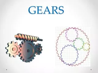
Gears. GEAR?. Power transmission is the movement of energy from its place of generation to a location where it is applied to performing useful work. A gear is a component within a transmission device that transmits rotational force to another gear or device. TYPES OF GEARS.

E N D
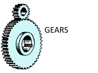
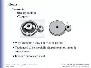
GEAR?.. • Power transmission is the movement of energy from its place of generation to a location where it is applied to performing useful work. • A gear is a component within a transmission device that transmits rotational force to another gear or device.
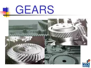
TYPES OF GEARS 1. According to the position of axes of the shafts. • Parallel shafts 1.Spur Gear 2.Helical Gear 3.Rack and Pinion b. Intersecting shafts Bevel Gear c. Non-intersecting and Non-parallel Worm and worm gears
SPUR GEAR • Teeth is parallel to axis of rotation • Transmit power from one shaft to another parallel shaft • Used in Electric screwdriver, oscillating sprinkler, windup alarm clock, washing machine and clothes dryer
HELICAL GEAR • The teeth on helical gears are cut at an angle to the face of the gear. • This gradual engagement makes helical gears operate much more smoothly and quietly than spur gears.
HERRINGBONE GEAR • To avoid axial thrust, two helical gears of opposite hand can be mounted side by side, to cancel resulting thrust forces • Herringbone gears are mostly used on heavy machinery.
Rack and pinion • Rack and pinion gears are used to convert rotation (from the pinion) into linear motion (of the rack). • A perfect example of this is the steering system on many cars.
BEVEL GEARS • Bevel gears are useful when the direction of a shaft's rotation needs to be changed • They are usually mounted on shafts that are 90 degrees apart, but can be designed to work at other angles as well • The teeth on bevel gears can be straight, spiral or hypoid • Applications include locomotives, marine applications, automobiles, printing presses, cooling towers, power plants, steel plants, railway track inspection machines, etc.
Bevel Gear • To transmit motion between shafts with axis intersecting with each other at certain angle • It has a conical form with teeth cut over the cone. Bevel gears with equal numbers of teeth and shaft axes at 90 degrees are called miter gears
WORM AND WORM GEAR • Worm gears are used when large gear reductions are needed. It is common for worm gears to have reductions of 20:1, and even up to 300:1 or greater • Many worm gears have an interesting property that no other gear set has: “the worm can easily turn the gear, but the gear cannot turn the worm”. • Worm gears are used widely in material handling and transportation machinery, machine tools, automobilesetc.
Pitch circle: It is an imaginary circle which by pure rolling action would give the same motion as the actual gear. • Pitch circle diameter: It is the diameter of the pitch circle. The size of the gear is usually specified by the pitch circle diameter. It is also known as pitch diameter. • Pitch point: It is a common point of contact between two pitch circles. • Pitch surface: It is the surface of the rolling discs which the meshing gears have replaced at the pitch circle. • Pressure angle or angle of obliquity: It is the angle between the common normal to two gear teeth at the point of contact and the common tangent at the pitch point. It is usually denoted by φ. The standard pressure angles are 14.5 ° and 20°.
TERMINOLOGIES CONTD.. Note : Root circle diameter = Pitch circle diameter × cos φ , where φ is the pressure angle. Circular pitch: It is the distance measured on the circumference of the pitch circle from a point of one tooth to the corresponding point on the next tooth. It is usually denoted by Pc. Mathematically, a little consideration will show that the two gears will mesh together correctly, if the two wheels have the same circular pitch.
TERMINOLOGIES CONTD.. Note : If D1 and D2 are the diameters of the two meshing gears having the teeth T1 and T2 respectively, then for them to mesh correctly
TERMINOLOGIES • Addendum:It is the radial distance of a tooth from the pitch circle to the top of the tooth. • Dedendum:It is the radial distance of a tooth from the pitch circle to the bottom of the tooth. • Addendum circle: It is the circle drawn through the top of the teeth and is concentric with the pitch circle. • Dedendum circle: It is the circle drawn through the bottom of the teeth. It is also called root circle.
Diametrical pitch: It is the ratio of number of teeth to the pitch circle diameter in millimetres. It is denoted by pd. Mathematically, Module: It is the ratio of the pitch circle diameter in millimeters to the number of teeth. It is usually denoted by m. Mathematically, Clearance: It is the radial distance from the top of the tooth to the bottom of the tooth, in a meshing gear. A circle passing through the top of the meshing gear is known as clearance circle. Total depth: It is the radial distance between the addendum and the Dedendum circles of a gear. It is equal to the sum of the Addendum and Dedendum.
Working depth. It is the radial distance from the addendum circle to the clearance circle. It is equal to the sum of the addendum of the two meshing gears. Tooth thickness. It is the width of the tooth measured along the pitch circle. Tooth space . It is the width of space between the two adjacent teeth measured along the pitch circle. Backlash. It is the difference between the tooth space and the tooth thickness, as measured along the pitch circle. Theoretically, the backlash should be zero, but in actual practice some backlash must be allowed to prevent jamming of the teeth due to tooth errors and thermal expansion.
Face of tooth: It is the surface of the gear tooth above the pitch surface. Flank of tooth: It is the surface of the gear tooth below the pitch surface. Top land: It is the surface of the top of the tooth. Face width: It is the width of the gear tooth measured parallel to its axis. Profile:It is the curve formed by the face and flank of the tooth. Fillet radius: It is the radius that connects the root circle to the profile of the tooth.
Forms of Teeth • In actual practice following are the two types of teeth commonly used 1. Cycloidal teeth 2. Involute teeth. Cycloidal Teeth • A cycloid is the curve traced by a point on the circumference of a circle which rolls without slipping on a fixed straight line. • When a circle rolls without slipping on the outside of a fixed circle, the curve traced by a point on the circumference of a circle is known as epi-cycloid. • On the other hand, if a circle rolls without slipping on the inside of a fixed circle, then the curve traced by a point on the circumference of a circle is called hypo-cycloid.
COMPARISON OF INVOLUTE AND CYCLOIDAL GEARS INVOLUTE GEARS CYCLOIDAL GEARS Since the Cycloidal teeth have wider flanks, therefore the Cycloidal gears are stronger than the involute gears, for the same pitch. Less wear in Cycloidal gears as compared to involute gears. In cycloidal gears, the interference does not occur at all. • The centre distance for a pair of involute gears can be varied within limits without changing the velocity ratio. • In involute gears, the pressure angle, from the start of the engagement of teeth to the end of the engagement, remains constant. • Involute teeth are easy to manufacture than Cycloidal teeth
COMPARISON OF INVOLUTE AND CYCLOIDAL GEARS INVOLUTE GEARS CYCLOIDAL GEARS Though there are advantages in cycloidal gears but they are outweighed by the greater simplicity and flexibility of the involute gears. • The only disadvantage of the involute teeth is that the interference occurs with pinions having smaller number of teeth.
Law of gearing • The common normal at the point of contact between a pair of teeth must always pass through the pitch point. • This is the fundamental condition which must be satisfied while designing the profiles for the teeth of gear wheels. It is also known as law of gearing.
Interference • The phenomenon when the tip of tooth undercuts the root on its mating gear is known as interference.
Gears - Problems • A single reduction gear of 120 kW with a pinion 250 mm pitch circle diameter and speed 650 r.p.m. is supported in bearings on either side. Calculate the total load due to the power transmitted, the pressure angle being 20°. Given : P = 120 kW = 120 × 103 W ; d = 250 mm or r = 125 mm = 0.125 m ; N = 650 r.p.m. or = 2 × 650/60 = 68 rad/s ; Ø= 20°