Download
1 / 57
910 likes | 1.52k Views
CHAPTER. Charging Systems. 7. Instructor Name: (Your Name ). Learning Objectives. Explain how an alternator produces a regulated DC voltage Describe how electrical contact is made through the rotating rotor windings Trace the current flow from the stator winding through a rectifier bridge

E N D
CHAPTER Charging Systems 7 Instructor Name:(Your Name)
Learning Objectives • Explain how an alternator produces a regulated DC voltage • Describe how electrical contact is made through the rotating rotor windings • Trace the current flow from the stator winding through a rectifier bridge • Explains haw a voltage regulator controls the strength of the rotors magnetic field
Learning Objectives (continued) • Define the purpose of the diode trio or the field diode assembly • Perform a preliminary inspection of a charging system • Disassemble and inspect the internal components of a typical alternator • Test a truck charging system • Perform a parasitic current draw test
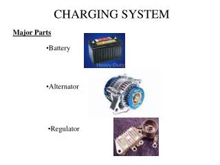
Alternators Role in the Electrical System • Recharges the trucks batteries • Primary power source when the truck is running • Produces AC voltage and converts it to DC with diodes • Regulates the voltage supplied to the system and the battery
Cutting Magnetic Lines of Force with a Conductor to Produce a Positive Voltage Figure 7-1 Cutting magnetic lines of force with a conductor to induce a voltage: conductor is moving from right to left through the magnetic field.
Cutting Magnetic Lines of Force with a Conductor to Produce a Negative Voltage Figure 7-2 Conductor has been moved from left to right through the magnetic field causing a reversal of polarity of induced voltage.
Inducing More Voltage • The greater the number of magnetic lines of force that are cut by a conductor per second, the greater the voltage that is induced in the conductor • Increase the speed of the conductor that moves through the magnetic field • Increase the strength of the magnetic field
Voltage Waveforms • An oscilloscope displays voltage amplitude on the y-axis and the time on the x-axis • The oscilloscope can be adjusted to change the values of each division of both the horizontal and vertical axis • 120 VAC from a wall socket would form a sine wave on the oscilloscope • The sine wave would alternate between positive and negative • This alternating polarity is where the term alternating current came from
Voltage Waveforms(continued) • The number of times a wave form repeats per seconds is called frequency and is measured in hertz
Simple Alternator Figure 7-8 Simple alternator.
Single Loop Rotating Through a Magnetic Field Figure 7-9 Single loop rotating in magnetic field at six different positions.
Voltage Wave Form Figure 7-10 Voltage waveform produced by a single loop rotating in a magnetic field.
Magnets Rotating Inside a Conductive Loop Figure 7-11 Magnet rotating inside of conductive loop induces an AC voltage in the loop.
Magnetic Field Lines of Force Flow Through a Stator Figure 7-12 Magnetic field lines of force flow through stator.
Electromagnet Rotating Inside Conductive Loop Figure 7-13 Electromagnet rotating inside of conductive loop induces an AC voltage in the loop.
Sine Wave Produced by Magnet Rotating Inside Conductive Loop Figure 7-14 Sinusoidal AC voltage waveform produced by rotating electromagnet inside of a conductive loop.
Three-Phase Power • Three-phase alternators have three conductive loops • Each loop is place 120° apart (360°÷3=120°) • Each loop will form a single sine wave voltage form with every revolution of the rotor
Three Conductor Stator and Output Sine Wave Figure 7-16 Three conductive loops connected together and spaced around the stator.
Three-Phase Sine Waveform Voltage Trace Figure 7-17 Three-phase sine waveform voltage trace.
Delta and Wye Wound Stators Figure 7-20 Stator winding arrangements.
Rotor Components Figure 7-21 Rotor components consist of coil and pole pieces installed on rotor shaft.
Alternating North and South Poles of Rotor and Magnetic Field Between Them Figure 7-22 Alternating north and south poles of rotor pieces produce a rotating magnetic field. Figure 7-23 Magnetic fields between adjacent rotor pole pieces surround the rotor.
Three-Phase Stator Winding Figure 7-24 Three-phase stator windings installed in laminated iron frame.
Converting AC to DC • AC current from alternator must be converted to DC current • Diodes, often called rectifiers, convert AC current to DC current • The output of the alternator stator windings is connected to a four diode bridge rectifier
Four Diode Bridge Rectifier Figure 7-27 Single-phase AC rectifier bridge.
Full Wave Rectification Figure 7-28 Full wave rectification reverses the polarity of the negative portion of a sine waveform.
Three-Phase Rectifier Requiring Six Diodes Figure 7-30 Three-phase rectifier requires six diodes.
Rectified Three-Phase Voltage Figure 7-31 Rectified three-phase voltage.
Voltage Regulation Fundamentals • Modern truck alternators are designed to maintain a 14.2V output for a 12V system • Voltage regulators maintain alternator output by controlling the current flow through the rotor field coil windings • If the alternator output is low, current to the rotor field coil is increased • If the alternator output is high, current to the rotor field coil is decreased
Switch Controlling Current Flow Figure 7-36 Switch shown as controlling current through rotor field coil through slip rings and brushes.
Voltage Regulation Fundamentals (continued) • Modern truck voltage regulators use pulse width modulation to control current flow to the rotor field coil • Pulse width refers to the on portion of a pulse compared to the off portion of a pulse • The longer the on portion a pulse has the more current supplied to the rotor field coil • The shorter the on portion a pulse has the less current supplied to the rotor field coil • Voltage for the rotor field coil is supplied by the diode trio or a field diode
Pulse Width Modulation Duty Cycle Figure 7-37 (A) Lights on for one time period and off for two time periods resulting in dim lamp output. (B) Lights on for two time periods and off for one time period resulting in brighter lamp output. Figure 7-38 Pulse width modulation (PWM). Duty cycle is the percentage of on-time per cycle.
Alternator Terminals and Circuits • Positive Output Terminal – insulated terminal marked BAT or B+. Normally connected to battery terminal of started and battery positive • Ground Terminal – Most truck alternators have a ground terminal that connects to the starter ground or frame. Some alternators ground through the alternator mounting bolts • Relay Terminal – Marked R or AC. Used on some systems to power relay only when engine is running
Alternator Terminals and Circuits (continued) • Indicator Light Terminal – Availableon some alternators. Dash indicator will light if alternator in not functioning. • Remote Sensing Terminal – Provides an indication of the battery voltage to the voltage regulator
Brushless Alternator Figure 7-42 Brushless alternator rotor and field coil.
Charging System Problems Complaints of High Charging Voltage Complaints of Low Charging Voltage Voltmeter reads too low Slow cranking speed or no crank Lamps that are too dim and turn signals that flash too slowly Decreased battery life • Voltmeter reads high • Sulfur smell • Wet batteries and high water usage • Lamps that are too bright and burn out quickly, turn signals that flash too rapidly • Decreased battery life
Tech Tip Testing a charging system using batteries that are not fully charged may lead you to an incorrect diagnosis. Recharging batteries can take a considerable amount of time. Having sufficiently charged batteries that you can temporarily install for testing can save you and your customer valuable time.
Delco Remy 28SI Alternator Figure 7-46 Delco Remy 28SI pad-mount alternator with serpentine drive belt and automatic tensioner.
CAUTION Each OEM has procedures for testing the charging system that should always be followed. Procedures listed are only examples and can not be performed on all vehicles.
Testing Alternator Charging Circuit Voltage Drop Figure 7-47 Testing alternator charging circuit voltage drop using carbon pile load tester, engine off.
Determining Individual Alternator Cable Voltage Drops Figure 7-48 Determining individual alternator cable voltage drops, engine off.
Alternator Output Test, No Load • Connect voltmeter across the alternator output positive and negative leads. Connect ammeter probe to alternator output lead. • Start engine, run at 1500 rpm for 2 minutes. • Observe voltage and current reading with all electrical loads off and engine running. • Conduct next test based on the results of test and chart below: Figure 7-49 Determining individual alternator cable voltage drops.
Test 1, Acceptable Unloaded Charging Voltage • Connect ammeter current probe to output lead of alternator • Connect carbon pile load tester across the battery terminal • Start engine, run at 1500 rpm, turn off all loads • Run 2 minutes with no electrical load • Adjust carbon pile until ammeter reads highest value. Quickly return carbon pile to the unloaded position.
Test 2, Low Alternator Output Voltage • Rotor lost residual magnetism. “Flashing the Field” may be required to start alternator charging. • Voltage regulator may be set too low • Full field the alternator to determine if the voltage regulator is faulty or if the alternator is faulty
WARNING Only perform a full field test if specified by the OEM. Use extreme caution when full fielding an alternator. The output voltage can rise to a very high level in a brief time and cause damage to the electrical system. It may also be very difficult to access the full fielding access hole on some alternators. Be careful when working around rotating components to avoid injury.
Test 3, High Charging Voltage • Possible faulty voltage regulator • Internal short to ground in the field coil • Voltage regulator set too high • Check OEM information for specific test for high charging voltage
CAUTION Never disconnect any battery or alternator cable when the engine is running. The rapid change in alternator output current can result in a very high alternator output voltage, which can destroy modern truck electronics. Never operate an engine without the batteries connected in parallel with the alternator output. This battery-less operation will cause the alternator output voltage to become very unstable, which could result in damage to electronic components.
Parasitic Draw Test • Turn off all electrical loads on truck. • Connect current ammeter probe on negative lead of battery. All other batteries may need to be disconnected. • Watch as the various modules power down. After a couple of minutes observe parasitic load current. • Using circuit diagram as a guide remove circuit protection devices one at a time until the parasitic load on ammeter drops off.
Testing Rotor With an Ohm Meter Figure 7-52 Testing for rotor field winding resistance. Figure 7-53 Testing for a short to ground field winding.
Testing Stator with an Ohmmeter Figure 7-54 Testing the stator for open circuits. Figure 7-55 Testing the stator for shorts to ground.