Download
1 / 31
580 likes | 1.01k Views
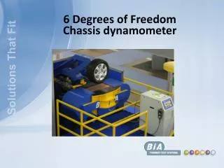
Geometry of five link mechanism with two degrees of freedom. David Tavkhelidze. Internal combustion engine. E. A-Crankshaft; B-Connecting rod; C-Slider (piston); D-Frame; E-Valve mechanism . Kinematic pairs. Degree of freedom. Degree of freedom for spatial mechanism.

E N D
Geometry of five link mechanism with two degrees of freedom David Tavkhelidze
Internal combustion engine E A-Crankshaft; B-Connecting rod; C-Slider (piston); D-Frame; E-Valve mechanism
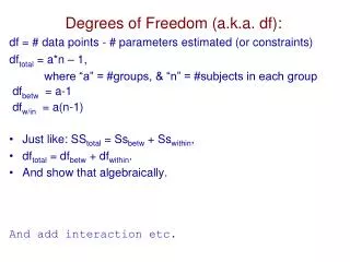
Degreeoffreedom Degree of freedom for spatial mechanism W=6n-P1-2P2-3P3-4P4-5P5 Degree of freedom of planar mechanism W=3n-2P5 3n=2P5
Mechanisms used in technological machines Four link slider - crank mechanism Four link mechanism with rotating kinematic pairs Five link mechanism with gear pair, reducing number degrees of freedom of the mechanical system Six link gear mechanism
Mechanisms with two degrees of freedom Kinematic scheme of five link mechanism with two degrees of freedom Various scheme of mechanisms with two degrees of freedom
. Straight geometrical task The design diagram of five link mechanism For the closed kinematic chain it is necessary that the product of matrices of transformation between coupled coordination systems connected with all incoming links has to be equal to unit matrix (1) For simplification of calculation it would be written (2)
Straight geometrical task The transformation matrix between of two sequential i-1 and i plain coordinate systems has the following general form: (3) Taking in the account the previous equations will be obtained (4)
Straight geometrical task , . The 4th matrix equation of five-link mechanism blockage contains full information about parameters of link motion characteristics. In order to determine relative and absolute displacement of links the respective elements of left and right parts of equation should be equated and receive system of algebraic equations the solution of which will enable to determine displacements of mechanism links. (5) . Besides these equations, in order to solve the problem the subsidiary condition should be added according to which the sum of internal angles of any five link is equal to 3π. (6)
, Straight geometrical task . . After transformations we get the following quadratic equation (7) Here: From the equation (7) we will obtain meanings of angelsϕ34and ϕ23 that determines position of the point C of the mechanism. (8) (9) And hence, in case of differentiating on time the received values of obtaining equations, we shall receive values of speeds and acceleration of the links of the mechanism.
The inverse geometrical task In spite of the straight geometrical problem, here on the basis of the given angels of rotation of the actuators mounted on the frame of the mechanism the trajectory of the output link of the considered mechanical system is defined. The formulation of inverse task of kinematics of five link mechanism is done in the following way: the location of C point of mechanism i.e. its coordinates in coordinate system connected with base, is given and it’s necessary to find generalized coordinates of the mechanism which provide the location of C point. The design diagram of five link mechanism for inverse task
The inverse geometrical task For this we take C point radius vector from the origin of coordinates and represent it as the sum of two vectors: (10) Projections of these vectors in immovable coordinate system are expressed as: (11) In projections formula (10) will have the following form: (12)
The inverse geometrical task In order to find two generalized and coordinates determining the location of BC kinematic chain the expressions (12) should be squared and summed up: (13) The obtained expressions (13) allows to calculate values of angels Hence, we will have: (14) (15) and
The inverse geometrical task We behave similarly when we determine the location of CDO kinematic chain. We present radius vector of C point in the form of the following vectors sum: (16) (17) (18) And hence we can obtain: Based on derivations of the given formulas the values of velocities and accelerations of the links of the investigated mechanism have obtained .
The inverse geometrical task Based on usage of MATLAB software here are given curves of alternations of phase angles of the five bar mechanism, when the two link junction point C is performing movement along the circle.
The inverse geometrical task Curves of alternation of angles
The inverse geometrical task Values of angular velocities
The inverse geometrical task Values of angular accelerations
Kinetostatics of five bar planar mechanisms On the links of mechanical system are acting two type of force factors - External forces and Internal forces. The internal forces – forces of weight, reduction forces of inertia and moments of inertia of force couples Forces of inertia- Moments of inertia of force couples-
Kinetostatics of five bar planar mechanism Reduction forces and moments of inertia acting on the links of five bar mechanism
Determination of forces and torques Lagrange equation relatively to generalized coordinate Lagrange equation relatively to generalized coordinate
Determination of forces and torques Equitant for determination of torque acting on Akinematic pair. Equitant for determination of torque acting on O kinematic pair.
Determination of force factors Determination of torque acting on Akinematic pair.
Determination of force factors Determination of torque acting on O kinematic pair.